Prosthetic mitral valve holders

a technology of mitral valve and holder, which is applied in the field of prosthetic mitral valve holders, can solve the problems of obstructing the visibility of posts or other parts, affecting the efficiency and/or general functionality of the heart, and affecting the operation of the holder, so as to reduce or eliminate the occurrence of suture looping, reduce or eliminate the effect of user error and simplified operation

Active Publication Date: 2020-07-28
EDWARDS LIFESCIENCES CORP
View PDF100 Cites 0 Cited by
  • Summary
  • Abstract
  • Description
  • Claims
  • Application Information

AI Technical Summary

Benefits of technology

[0009]Attempts have been made to resolve the issue of suture looping, some of which involve holders, which hold the prosthetic valves during delivery of the valves to the native valve annulus. In one example, a holder has a mechanism that urges the commissure posts of the prosthetic valve radially inwardly during delivery, such that the ends of the commissure posts are pointed inwards, to reduce the possibility of sutures catching against or looping around the commissure posts. After the valve prosthesis is delivered to the implant site, the holder is removed thereby releasing and expanding the commissure posts to their original positions. However, such holders may not be amenable to minimally invasive surgical techniques as the holder and valve combination may have a high or large profile, for example with the entire holder system positioned outside the valve, or the holder may not pull in the commissures enough to reduce the valve profile.
[0014]Features of the present disclosure provide for new holder systems and methods of using the holder systems, which reduce or eliminate the occurrence of suture looping or other damage to the prosthetic valves during implantation, for example, for mitral valve replacement using minimally invasive procedures or other procedures. Operation of the holders is also simplified, whereby the valves are prevented from being implanted prior to deployment of the holders, for example, via a removable activator dial, thereby reducing or eliminating mistakes caused by user error. According to embodiments, the dial cannot be removed until the system is activated, and while in place, the activator prevents the valve from being implanted. In some embodiments, the holder includes a removable handle that cannot be connected to the system until the removable activator dial is removed. The holders also provide for integrated alignment features or other safety features, such that over-deployment or under-deployment of the holders is prevented.
[0015]According to embodiments of the invention, holders for prosthetic valve delivery reduce or eliminate occurrences of suture looping and / or other damage to the valves when the valves are implanted, while the mechanisms for deploying these features are integrated into the holders in a way that reduces or eliminates mistakes in use and deployment.
[0016]In some embodiments, a mitral valve holder and handle system is provided that uses a ratchet mechanism to pull in the commissures of the valve towards the center of the valve, thereby eliminating the risk of suture looping. The holder has mistake-proofing features that prevent the physician from implanting the valve without engaging the system. In some embodiments, by flattening the profile of the valve, the holder system can allow implantation of the valve through a small or minimal incision. According to some embodiments, an introducer is provided to aid in implanting replacement valves through a minimal size incision, for example, by aiding in collapsing or otherwise reducing the profile of the valve and / or valve holder. The introducer can be used, for example, with mitral and / or aortic surgical valves. In some embodiments, such an introducer can be relatively short and only long enough to pass the valve past a patient's ribs. In other embodiments, the introducer can be relatively long and, for example, act as an atrial retractor, forming a channel all the way to the implant site in the case of a mitral valve.

Problems solved by technology

When a valve become diseased or damaged, leakage or regurgitation may occur, where some of the blood travels back upstream through the diseased or damaged valve, and the efficiency and / or general functionality of the heart may be compromised.
Meanwhile, in some cases, the prosthetic valves are implanted through small access channels using one of various minimally invasive surgical procedures, where visibility at the implant site may be impeded or obstructed.
In addition, depending on the direction of implantation, for example, with some mitral valve replacement procedures, commissure posts of the stent or frame, or other portions, of the prosthetic valve may be pointed distally and advanced on a blind side of the valve, thereby obstructing visibility of the posts or other portions during advancement and implantation.
This type of entanglement of sutures with prosthetic valves is referred to as “suture looping,” which specifically refers to instances where a suture is inadvertently wrapped around one or more of the commissure post tips, where it can then migrate towards and damage the leaflets or interfere with proper leaflet coaptation or other valve operation when the sutures are tightened or secured, resulting in improper valve operation.
In some cases, such tangling may not be apparent to the practitioner at the time of implantation, and will only be revealed some time later when valve operation is observed to be improper or other complications arise in the patient, in which case, it may be necessary to initiate another procedure to repair or replace the prosthetic valve.
In addition, many existing bioprosthetic valves are not amenable to implantation through a minimal size incision, such as in thoracotomy procedures.
However, such holders may not be amenable to minimally invasive surgical techniques as the holder and valve combination may have a high or large profile, for example with the entire holder system positioned outside the valve, or the holder may not pull in the commissures enough to reduce the valve profile.
However, this system may not be very amenable to a minimally invasive surgical approach.
The system does not pull in the commissures enough to reduce the valve profile, and the central post of the holder adds to the overall height of the valve once deployed, hindering minimally invasive surgical procedures.
In addition to the above, many of the newer holder designs also incorporate many additional parts that must be assembled by the practitioner or other end user, which may also lead to additional complications.
Many of these holders have proven to be too complicated and / or prone to user error.
Consequently, when practitioners use these holders improperly, suture looping still commonly occurs, while the implant process may also be further complicated by issues arising from user error.
Tightening too little can make the holder ineffective to prevent suture looping, while over-tightening can risk breaking one or more sutures of the system or damaging the valve.
However, such holders and valves may not include a mechanism to actively collapse the valve into the reduced size configuration for delivery.

Method used


Image

  • Prosthetic mitral valve holders
  • Prosthetic mitral valve holders
  • Prosthetic mitral valve holders

Examples


first embodiment

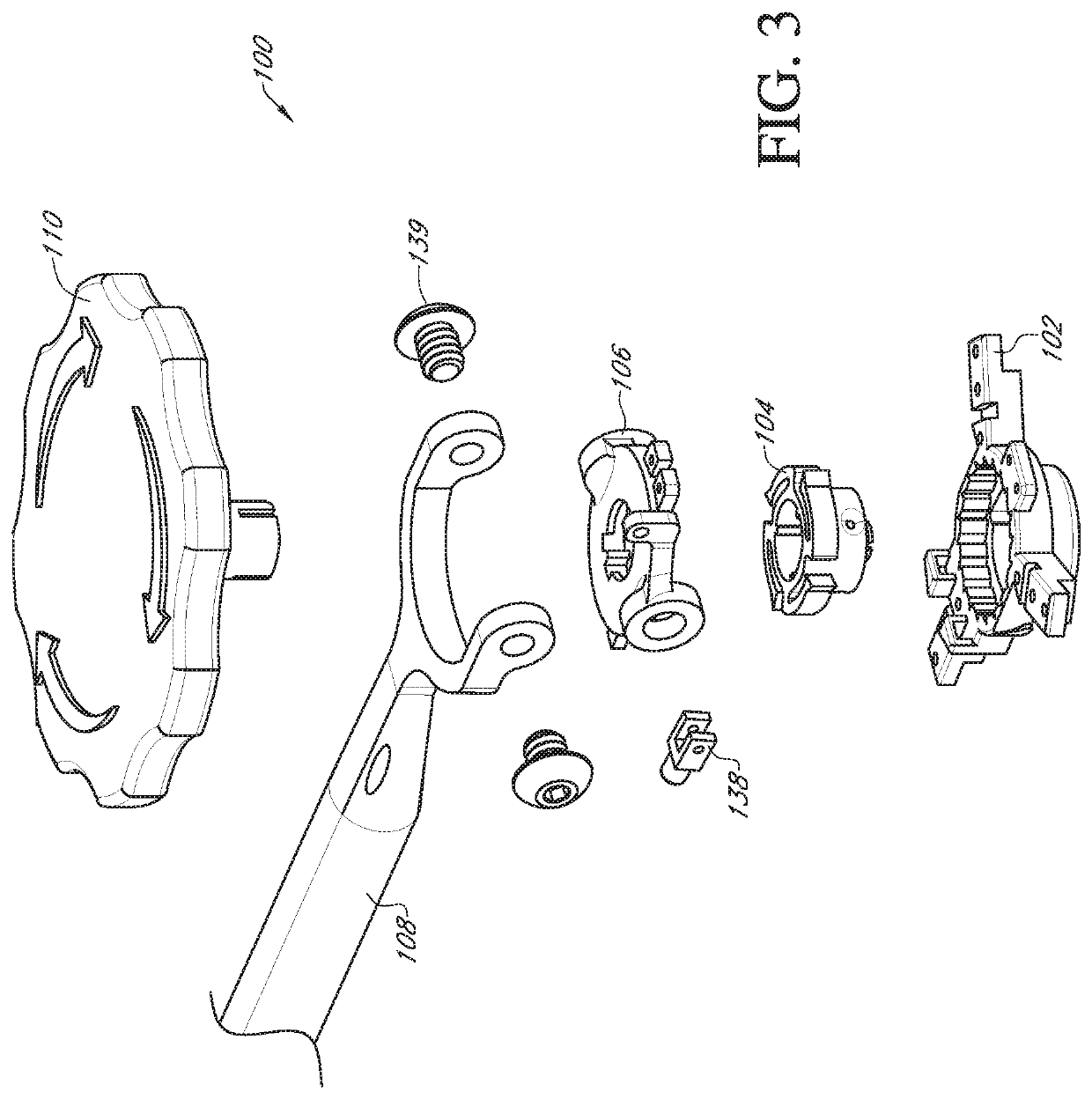
[0052]FIGS. 3 to 5 show views of a valve holder 100 according to a FIG. 3 shows an exploded perspective view of the valve holder 100, FIG. 4 shows a perspective view of the valve holder 100 in an assembled state, and FIG. 5 shows a cross-sectional view of the valve holder 100 in the assembled state.

[0053]The valve holder 100 includes a body 102, a rotor 104, a swiveling delivery mount 106, a delivery handle 108, and an activator dial 110. As described in more detail below, a prosthetic heart valve can be attached to the body 102. The rotor 104 is positioned in a bore of the body 102 and is adjustable using the dial 110 to deploy or activate the valve holder 100 to adjust the prosthetic valve to a delivery position or configuration. The delivery mount 106, coupled to the delivery handle 108, is attached to the body 102 for delivering the valve to the implant site. The prosthetic valve can include a Nitinol wireform exhibiting a large amount of flexibility.

[0054]The body 102 of the v...

third embodiment

[0087]FIGS. 18A to 20 show views of a valve holder 300 according to a FIG. 18A shows an exploded perspective view of the valve holder 300, FIG. 18B shows a perspective view of an underside of a guide 306 of the valve holder 300, FIG. 18C shows a perspective view of an activator dial 310 of the valve holder 300, FIG. 19 shows a perspective view of the valve holder 300 in an assembled state, and FIG. 20 shows a cross-sectional view of the valve holder 300 in the assembled state.

[0088]The valve holder 300 of the third embodiment allows the use of an inexpensive, reusable handle system, with a mitral valve holder that is activated or deployed to reduce or eliminate the occurrence of suture looping. As in the first and second embodiments, the valve holder 300 of the third embodiment includes integrated alignment features or other safety features, such that over-deployment or under-deployment of the valve holder 300 is prevented or avoided. The valve holder 300 of the third embodiment di...


PUM


Abstract

Valve holders and introducers for delivering a prosthetic heart valve to an implant site are in various embodiments configured to facilitate insertion of prosthetic valves through small incisions or access sites on a patient's body. The valve holders can also be configured to reduce or eliminate the occurrence of suture looping or other damage to the prosthetic valve during implantation. A valve holder according to embodiments of the invention includes features that reduce or eliminate mistakes during implantation of the prosthetic valves, for example, a removable activator dial and a removable handle that prevent implantation of the valve prior to proper deployment or adjustment of the holder. An introducer is provided which can facilitate passing of a prosthetic valve between adjacent ribs of a patient. Valve holders and introducers according to the various embodiments can be used in minimally invasive procedures, such as thoracotomy procedures.

Description

CROSS-REFERENCE TO RELATED APPLICATION[0001]This application claims the benefit of U.S. Patent Application No. 62 / 417,207, filed Nov. 3, 2016, the entire disclosure of which is incorporated by disclosure.BACKGROUNDField[0002]The present disclosure generally concerns medical devices, deployment mechanisms, and methods for deploying such medical devices. More specifically, the disclosure relates to surgical replacement of native heart valves that have malformations and / or dysfunctions. The present disclosure also relates to prosthetic heart valves, and specifically, prosthetic mitral valves that can be implanted through a minimal sized incision. Embodiments of the invention relate to holders for facilitating the implantation of bioprosthetic replacement heart valves at native heart valves, for example, for a mitral valve replacement procedure. Embodiments of the invention also relate to methods of using the holders to facilitate implantation of prosthetic heart valves.Description of R...

Claims


Application Information

Patent Timeline
Patent Type & Authority Patents(United States)
IPC IPC(8): A61F2/24A61B17/00A61F2/95
CPCA61F2/2427A61B17/00234A61B2017/00398A61F2/2418A61B2017/00477A61F2/9517A61B2017/00407
Inventor CONKLIN, BRIAN S.JOHNSON, DERRICK
Owner EDWARDS LIFESCIENCES CORP
Why Eureka
Try Eureka