System for humidification of medical gases

a technology for humidification systems and medical gases, which is applied in the field of systems for humidification of medical gases, can solve the problems of increasing the number of set-up steps, reducing the portability of the system, and requiring large volumes of liquid, so as to reduce or eliminate the effect of reducing or eliminating the likelihood of the generated vapour entering the atmosphere and reducing the likelihood of the generated vapour

Active Publication Date: 2020-07-28
FISHER & PAYKEL HEALTHCARE LTD
View PDF13 Cites 0 Cited by
  • Summary
  • Abstract
  • Description
  • Claims
  • Application Information

AI Technical Summary

Benefits of technology

[0009]In an embodiment, the humidification system comprises a bead that is configured to absorb or hold a liquid. The bead is spirally wound with an outer layer to form a tube. The tube is pre-loaded such that sufficient liquid is stored within the bead. A heating mechanism is integral to the tube and supplies heat to the bead to release vapour and to increase the gases temperature to above ambient temperature. The outer layer provides a barrier to reduce or eliminate the likelihood of the generated vapour entering the atmosphere. Gases flowing through the tube are heated and humidified by the vapour that is released from the bead. Heat is also supplied to the gases by the heating mechanism. The heating mechanism is connected with an external power supply.
[0010]The tube comprises a small diameter and lightweight construction. Thus, the humidification system is easily integrated into a surgical environment. Liquid required for the surgical procedure is stored within the bead material. Flexibility of the tube is maintained when liquid is stored within the bead. The liquid is released as vapour upon application of heat. The bead is configured to provide structural support to the tube.
[0011]The humidification system comprises minimal set-up steps due to the integrated tube design. For example, there is no need for an external liquid reservoir to supply the system with sufficient liquid for the surgical procedure. Similarly, there is no need for a wick to convey liquid into the tube so that humidification can take place. The tube is not dependent on a specific orientation for functionality, which gives the medical practitioner more freedom to manipulate the system.

Problems solved by technology

Humidification systems can have a large footprint and require large volumes of liquid for humidification to take place.
An external liquid supply reduces the portability of the system, increases the number of set-up steps, and thus increases the overall complexity of the system.
The system also requires a large portion of the limited space within a surgical theatre.
Liquid held in reservoirs within the tube increases the weight and reduces the flexibility of the tube, thereby making the tube difficult to manipulate within the surgical space.

Method used


Image

  • System for humidification of medical gases
  • System for humidification of medical gases
  • System for humidification of medical gases

Examples


Embodiment Construction

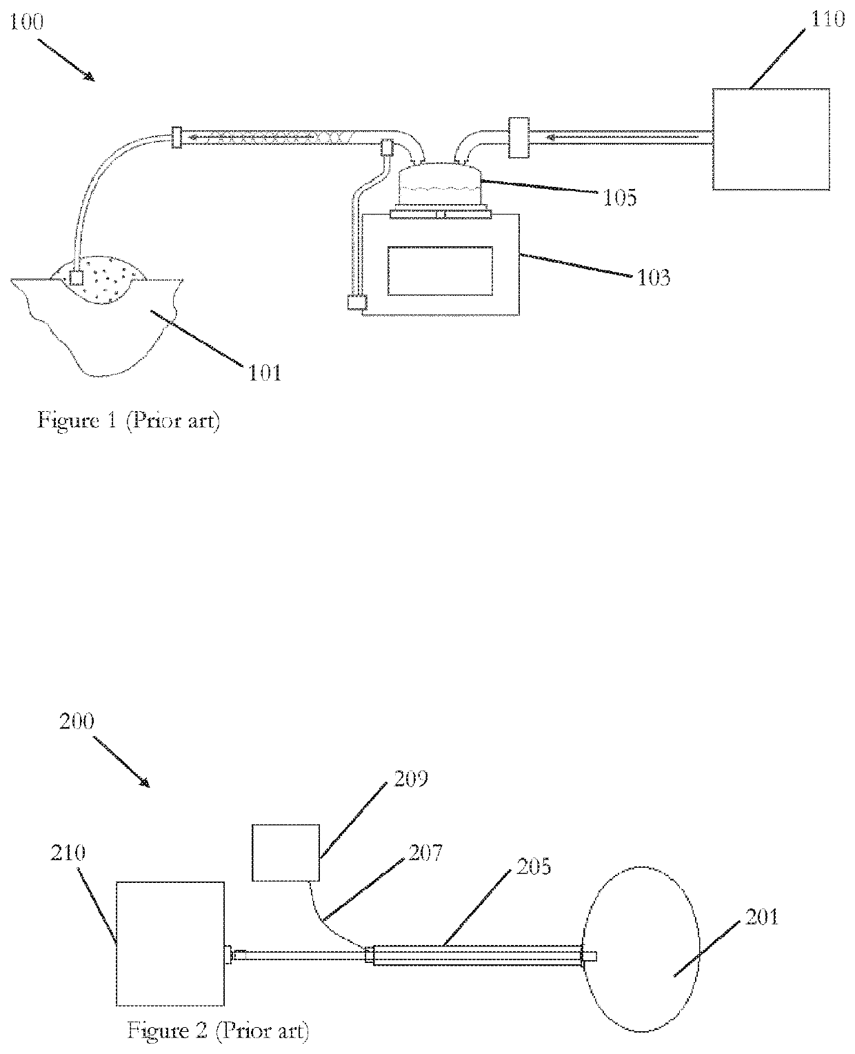
[0040]FIG. 1 illustrates a prior art humidification system 100 that is configured to deliver heated and humidified gases to a patient 101. The humidification system 100 comprises a humidification apparatus 103, a humidification chamber 105, and a gases source 110. In an embodiment, the gases source 110 is an insufflator. The humidification chamber 105 is configured to hold water. The humidification apparatus 103 comprises a heating mechanism configured to heat the water within the humidification chamber 105 to form water vapour. Gases from the gases source 110 are heated and humidified as they pass through the humidification chamber 105 and the conditioned gases are delivered to the patient 101.

[0041]Gases as herein described refers to respiratory gases (for example, oxygen, air, nitrogen, carbon dioxide, or a combination of any of these), or surgical gases, (for example, carbon dioxide, nitrous, oxygen, air, helium, or a mixture of carbon dioxide with nitrous or oxygen). Other gase...


PUM


Abstract

A humidification system has a tube configured to transport gases. The tube is configured to be soaked prior to use and has a bead to hold liquid. Heat applied to the bead causes the liquid to be released as vapour. Gases flowing through the tube are heated and humidified by the vapour.

Description

INCORPORATION BY REFERENCE TO ANY PRIORITY APPLICATIONS[0001]Any and all applications for which a foreign or domestic priority claim is identified in the Application Data Sheet as filed with the present application are hereby incorporated by reference under 37 CFR 1.57. This application hereby incorporates by reference U.S. Prov. App. No. 62 / 112,784 filed on Feb. 6, 2015 in its entirety.BACKGROUNDTechnical Field[0002]The present disclosure generally relates to a system for the humidification of medical gases. More particularly, the present disclosure relates to a system for the humidification of medical gases using an integrated tube humidifier.Description of the Related Art[0003]A humidification apparatus is used to provide heated and humidified gases to a patient via a patient interface. Humidified medical gases protect the peritoneum from desiccation and inflammation caused by cold dry gases used during surgical procedures.[0004]Pass-over humidification devices supply heated, hum...

Claims


Application Information

Patent Timeline
Patent Type & Authority Patents(United States)
IPC IPC(8): A61M13/00A61M16/08A61M16/10A61M16/14A61B17/34A61M16/16
CPCA61M16/145A61M16/0875A61M16/1095A61M16/16A61B17/3474A61M13/003A61M16/109A61M2210/1017A61M2205/3653
Inventor BOYES, RICHARD JOHNFISCHER, CHRISTIAN FRANCISSTREVENS, JOSEPH PATRICK WALTERSTOKS, ELMO BENSONMALLINSON, JAYANANDA
Owner FISHER & PAYKEL HEALTHCARE LTD
Why Eureka
Try Eureka