Method for assisted upshifting and device for this purpose

Active Publication Date: 2020-07-28
MAN NUTZFAHRZEUGE AG
View PDF22 Cites 0 Cited by
  • Summary
  • Abstract
  • Description
  • Claims
  • Application Information

AI Technical Summary

Benefits of technology

[0004]The object of the invention is to provide an improved method for assisted upshifting and a device for this purpose,

Problems solved by technology

Depending on the location of the flap (upstream or downstream of an exhaust turbocharger) it can take a relatively long time to reduce the engine speed, since the exhaust gas has to be built up upstream of the flap as far as the com

Method used


Image

  • Method for assisted upshifting and device for this purpose
  • Method for assisted upshifting and device for this purpose
  • Method for assisted upshifting and device for this purpose

Examples


Example

DETAILED DESCRIPTION OF THE DRAWINGS

[0070]The embodiments shown in the figures correspond at least partially to one another, so that similar or identical parts are provided with the same reference numerals and are also explained through reference to the description of the other embodiments and figures, in order to avoid repetitions.

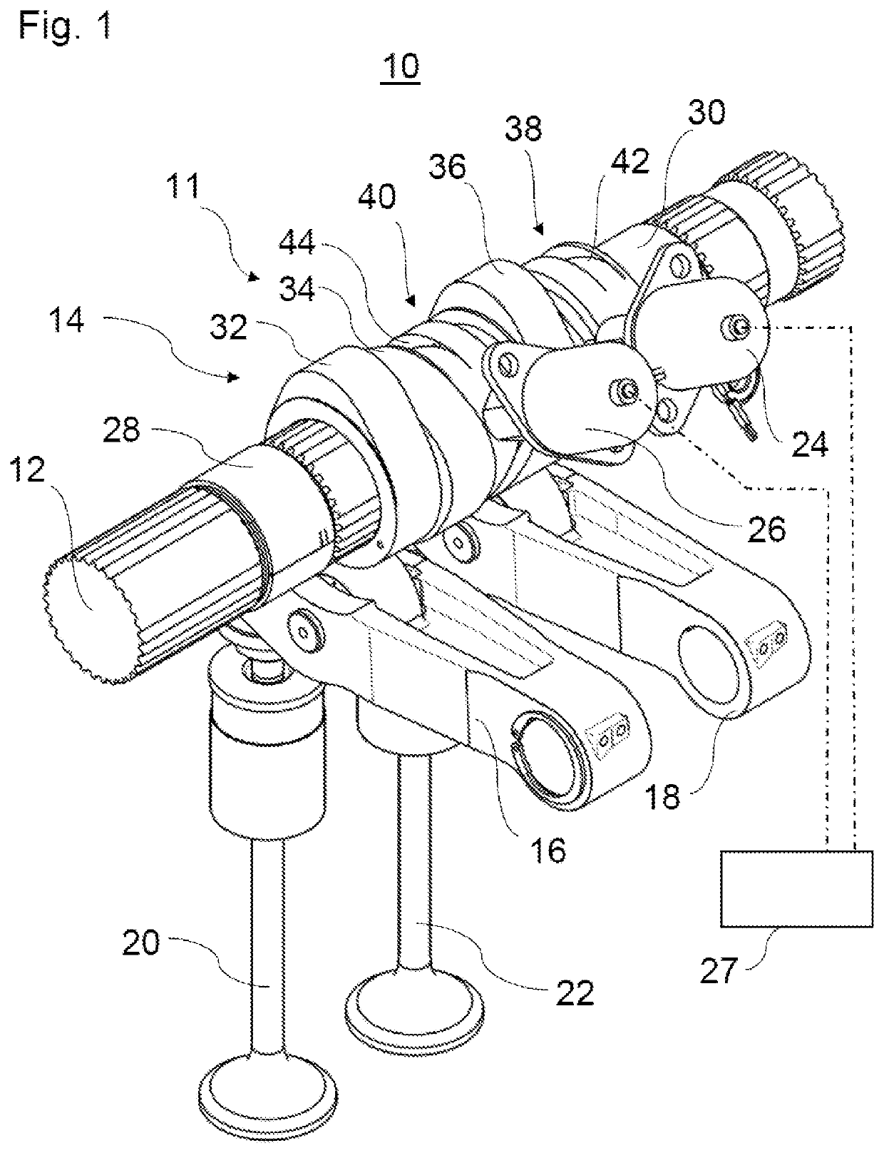
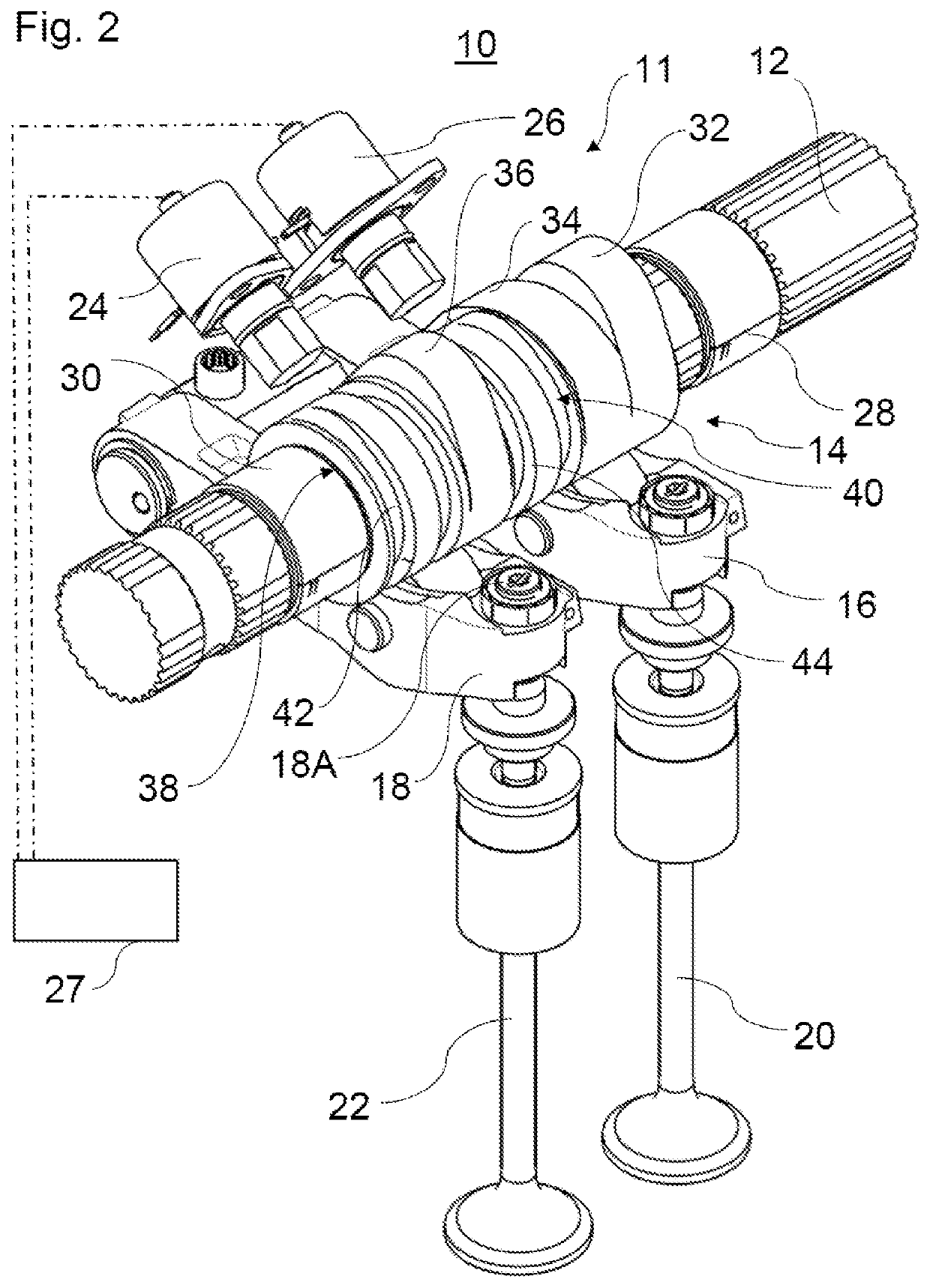
[0071]FIGS. 1 and 2 show a variable valve gear 10. The variable valve gear 10 comprises a camshaft 12 and a cam carrier 14. In addition, the variable valve gear 10 comprises a first and second transmission device 16 and 18 together with a first and second exhaust valve 20 and 22. The variable valve gear 10 moreover comprises a first actuator 24 and a second actuator 26. The cam carrier 14, the transmission devices 16 and 18 and the actuators 24 and 26 form a trip cam system 11.

[0072]The camshaft 12 is embodied as an exhaust camshaft, which actuates exhaust valves 20 and 22. The camshaft 12 is part of a double camshaft system (not represented in detail), w...


PUM


Abstract

The invention relates to a method for assisted upshifting in a gear change of a transmission connected to a combustion engine. The method comprises the initiation of an upshifting process. The method comprises the reduction of an engine speed of the combustion engine by switching to an engine-braking mode, wherein a variable valve gear, in particular a trip cam system, of the combustion engine serves for switching to the engine-braking mode. Alternatively or in addition, in the engine-braking mode a first exhaust valve of the combustion engine is at first kept closed during the compression stroke and/or during the exhaust stroke for the compression of air and is opened before reaching a top dead centre of a piston movement for decompression of the compressed air.

Description

TECHNICAL FIELD[0001]The invention relates to a method for assisted upshifting and to a variable valve gear.BACKGROUND OF THE INVENTION[0002]In the field of commercial vehicles, the reduction in engine speed in order to bring the engine and transmission speeds into line with one another when shifting up a gear is typically facilitated by means of existing engine-brake flaps. Depending on the location of the flap (upstream or downstream of an exhaust turbocharger) it can take a relatively long time to reduce the engine speed, since the exhaust gas has to be built up upstream of the flap as far as the combustion chamber. The piston must expel the exhaust gas in the cylinder in opposition to the accumulated exhaust gas in the exhaust tract. Additional work is involved. As a result, the engine speed is reduced.[0003]Besides the length of time involved in reducing the engine speed by means of the engine-brake flap, the known method has the further disadvantage that a turbocharger lag can...

Claims


Application Information

Patent Timeline
IPC IPC(8): F02D41/02F02D41/00F16H63/50F02D13/04F02D13/02
CPCF02D41/0007F02D13/04F02D13/0246F02D41/023F16H63/50F02D13/0257F02D2200/101F02D2041/001Y02T10/12
Inventor HIRSCHMANN, STEFFENMALISCHEWSKI, THOMASHYNA, DOMINIC
Owner MAN NUTZFAHRZEUGE AG
Why Eureka
Try Eureka