Method for directly forming patterns on face membrane by vacuum absorption

Inactive Publication Date: 2009-12-31
CHOU LUNG WEN
View PDF9 Cites 10 Cited by
  • Summary
  • Abstract
  • Description
  • Claims
  • Application Information

AI Technical Summary

Benefits of technology

[0007]This invention is devised to offer a method for directly forming patterns on face membrane by vacuum absorption. Firstly, polyurethane (PU), after foamed, is injected on the surface of a substratum cloth to form a face membrane thereon. Next, the face membrane is heated at a preset temperature by a pre heating box to continuously keep the face membrane in a softened condition before it is thoroughly hardened. An airproof release film is afterward attached on one side of the substratum cloth opposite to the face membrane. Then, a roller, having fu

Problems solved by technology

Moreover, in the producing process, many devices are necessary, thus r

Method used


Image

  • Method for directly forming patterns on face membrane by vacuum absorption
  • Method for directly forming patterns on face membrane by vacuum absorption
  • Method for directly forming patterns on face membrane by vacuum absorption

Examples


Example

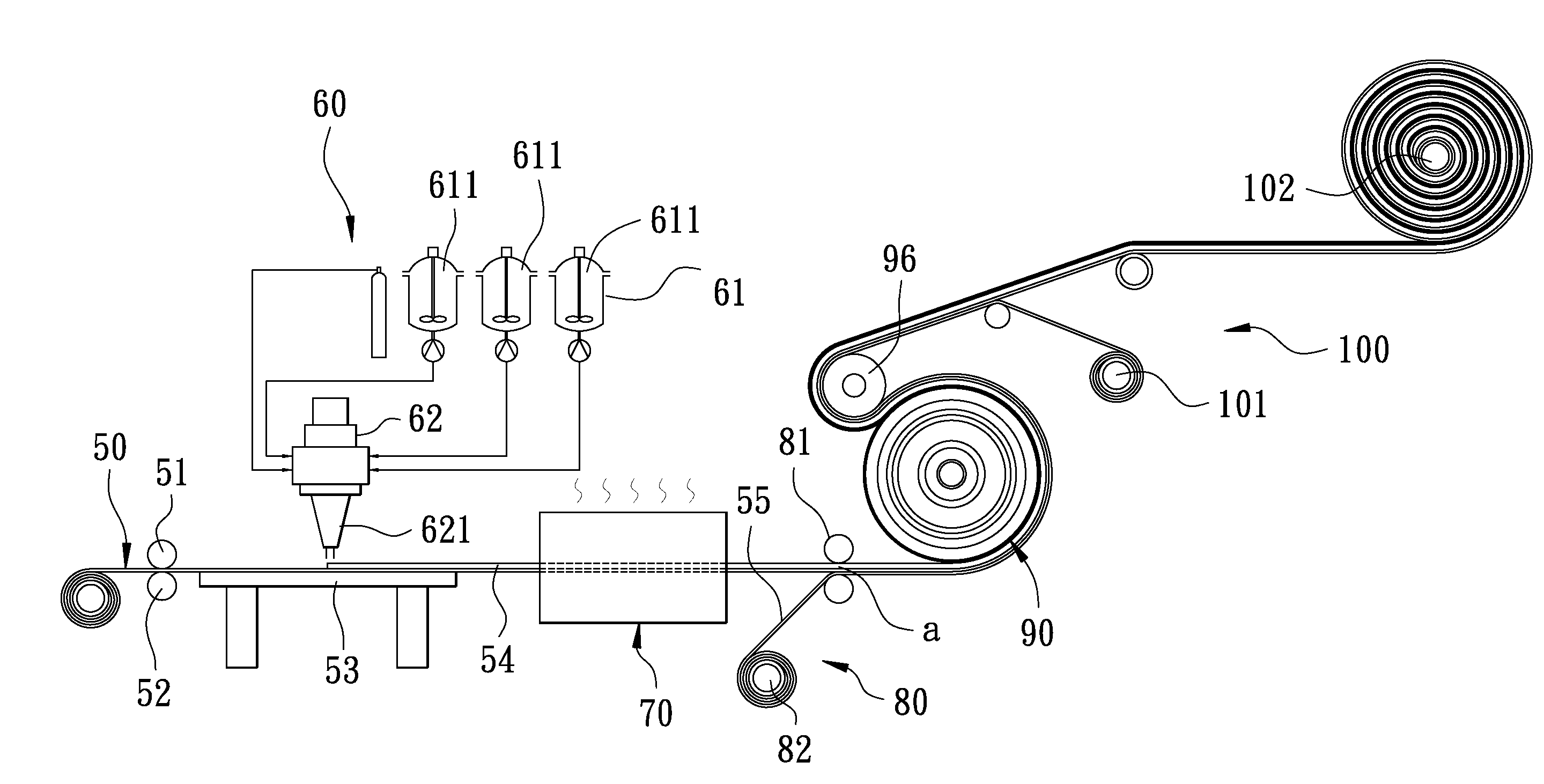
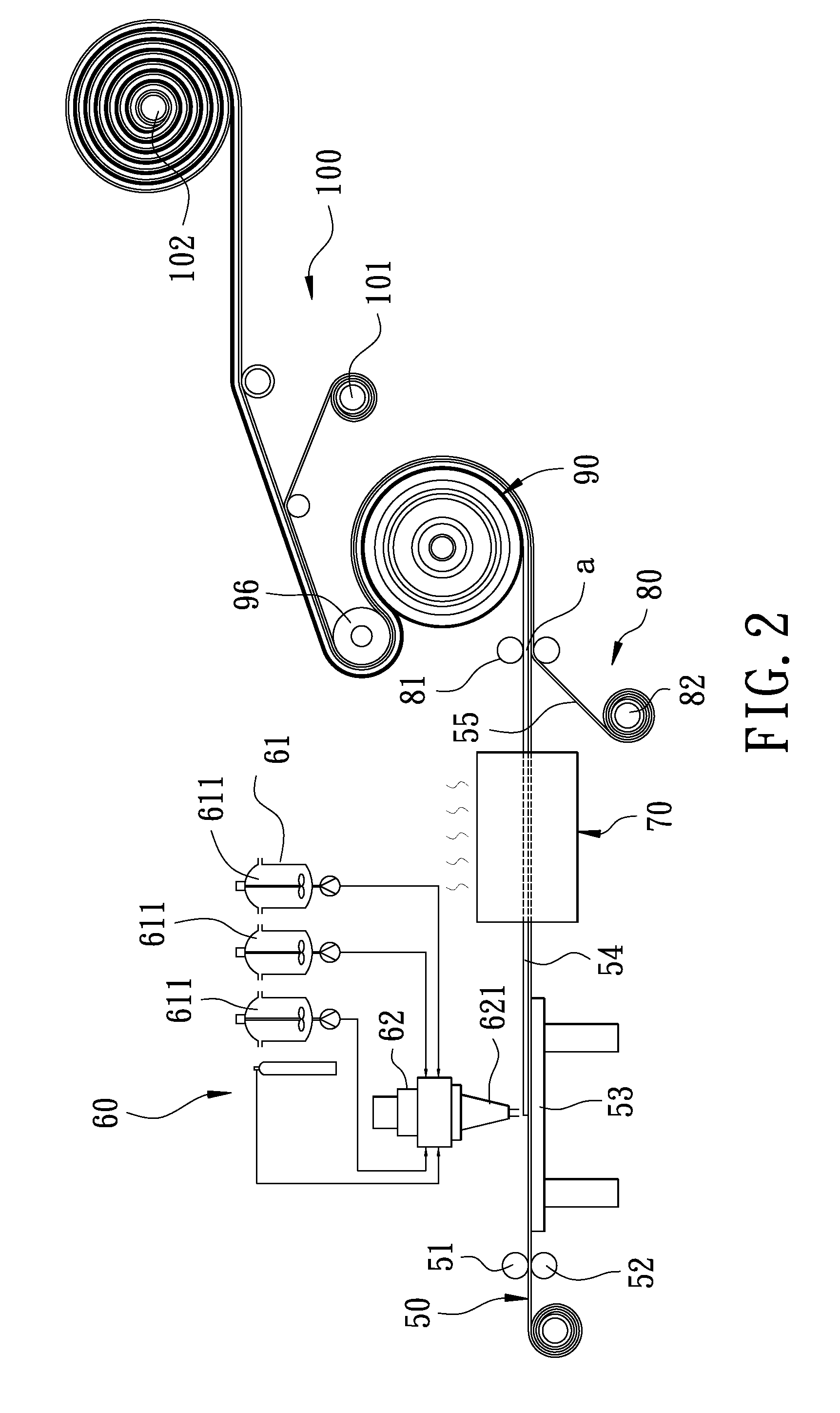
[0012]A preferred embodiment of a method for directly forming grains on face membrane by using the air-drawing force of vacuum in the present invention, as shown in FIG. 2, includes the following steps.

[0013]A first step is to prepare substratum cloth 50 made of fabric, non-woven fabric, extra fine fiber or the like. The substratum cloth 50 is dragged through and pressed between an upper roller 51 and a lower roller 52 synchronously and conveyed forward neatly along the topside of a work bench 53.

[0014]A second step is to provide an injecting installation 60 positioned above the substratum cloth 50 on the workbench 53. The injection installation 60 consists of a material device 61 and a material-mixing device 62, and the material device 61 contains three material tanks 611 respectively filled therein with liquid isocyanate polymer hydroxyl compound, a foaming agent and a pigment. The three material tanks 611 are respectively connected with the material mixing device 62 so that diffe...


PUM

PropertyMeasurementUnit
Temperatureaaaaaaaaaa
Forceaaaaaaaaaa

Abstract

A method for forming patterns on face membrane by air-drawing force when vacuum. A foamed polyurethane (PU) is injected on the surface of substratum cloth to form a face membrane. The face membrane is heated at a preset temperature by a preheating box to be continuously maintained in a softened condition before it is not thoroughly hardened. An airproof release film is attached on one side of the substratum cloth opposite to the face membrane. A roller having functions of vacuum and cooling has its superficial patterns being pressed and printed on the heated face membrane by the air-drawing force when vacuum.

Description

RELATED APPLICATION[0001]The present application is a continuation-in-part and claims benefit of the co-pending U.S. patent application Ser. No. 11 / 776,609, Method For Directly Forming Patterns On Face Membrane By Vacuum Absorption, filed on Jul. 12, 2007.BACKGROUND OF THE INVENTION[0002]1. Field of the Invention[0003]This invention relates to a PU face membrane, particularly to one having patterns directly formed thereon by means of vacuum absorption.[0004]2. Description of the Prior Art[0005]Referring to FIG. 1, a conventional way of forming a face skin on a basic material is to have substratum cloth 10 conveyed forward on a workbench in a preset direction. The substratum cloth 10 is made of fabric, non-woven fabric, extra fine fiber or the like. A first material-injecting device 20 is positioned above the substratum cloth 10 for injecting PU resin and foaming material on the surface of the substratum cloth 10 to form a PU foam layer 11 and then a first-layer separable paper 12 is...

Claims


Application Information

Patent Timeline
IPC IPC(8): B05D1/38
CPCB32B27/12B32B27/40B32B38/06B32B2305/18D06N3/14D06N3/005D06N3/0077D06N3/0079B32B2375/00B32B3/30B32B5/022B32B5/18B32B5/245B32B7/06B32B27/18B32B27/32B32B2250/02B32B2266/0278B32B2307/7242
Inventor CHOU, LUNG-WEN
Owner CHOU LUNG WEN
Why Eureka
Try Eureka