Melting furnace for metallurgical plant and operating method therefor

Active Publication Date: 2021-03-18
DANIELI & C OFF MEC SPA
View PDF0 Cites 0 Cited by
  • Summary
  • Abstract
  • Description
  • Claims
  • Application Information

AI Technical Summary

Benefits of technology

[0019]It is the aim of the present invention to provide a melting furnace and an operating method thereof, which ensure

Problems solved by technology

This produces extremely high temperatures, which make the metal material melt and liquefy, whereby causing the formation of a metal bath and a foamy layer, called slag, on the surface of said metal bath.
A single charge

Method used


Image

  • Melting furnace for metallurgical plant and operating method therefor
  • Melting furnace for metallurgical plant and operating method therefor
  • Melting furnace for metallurgical plant and operating method therefor

Examples


Example

[0048]The same reference numbers in the figures identify the same elements or components.

DETAILED DESCRIPTION OF PREFERRED EMBODIMENTS OF THE INVENTION

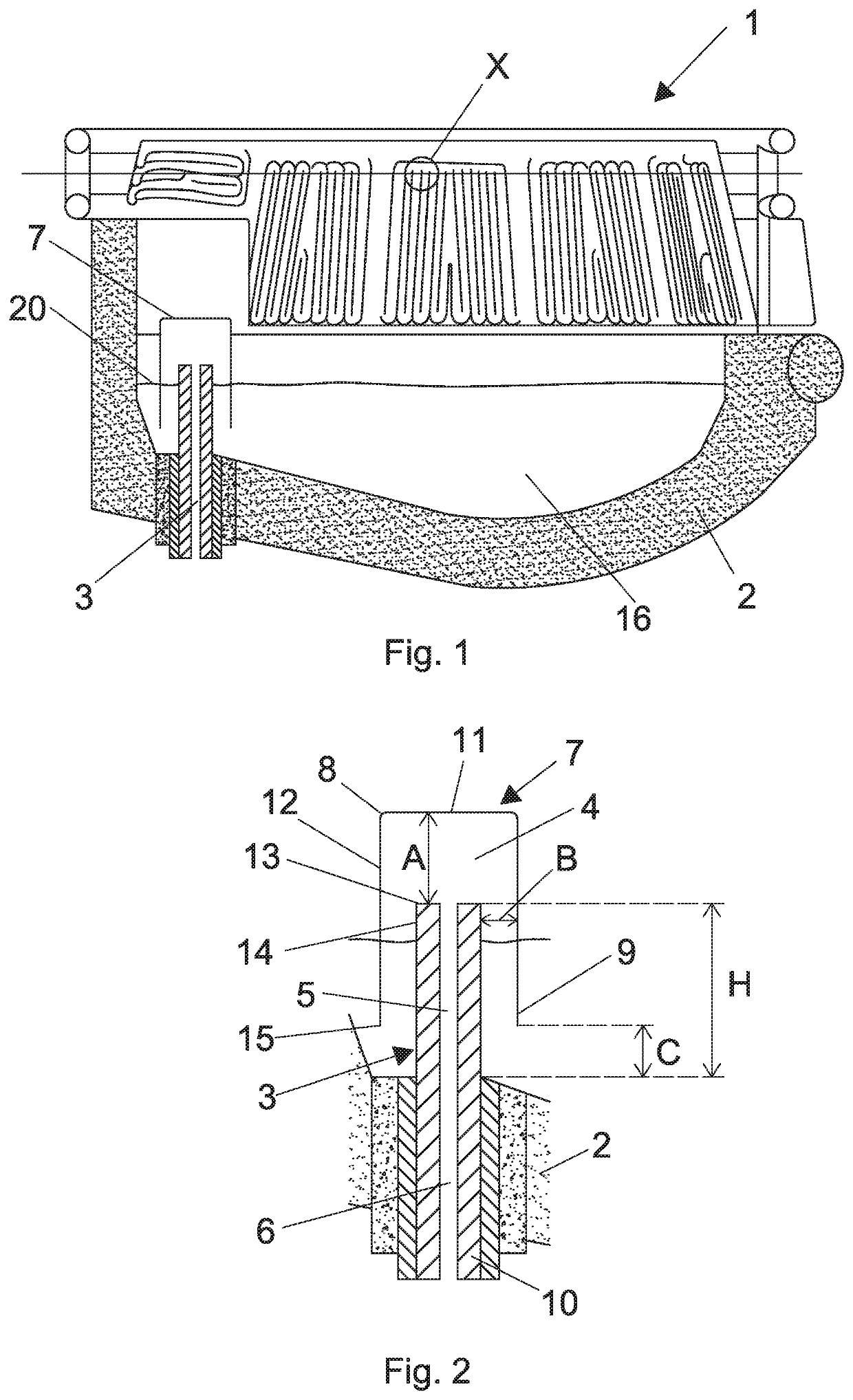
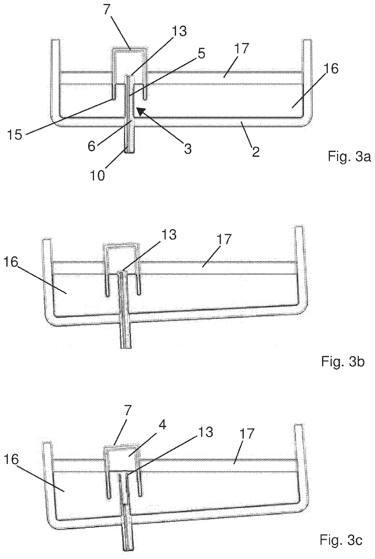
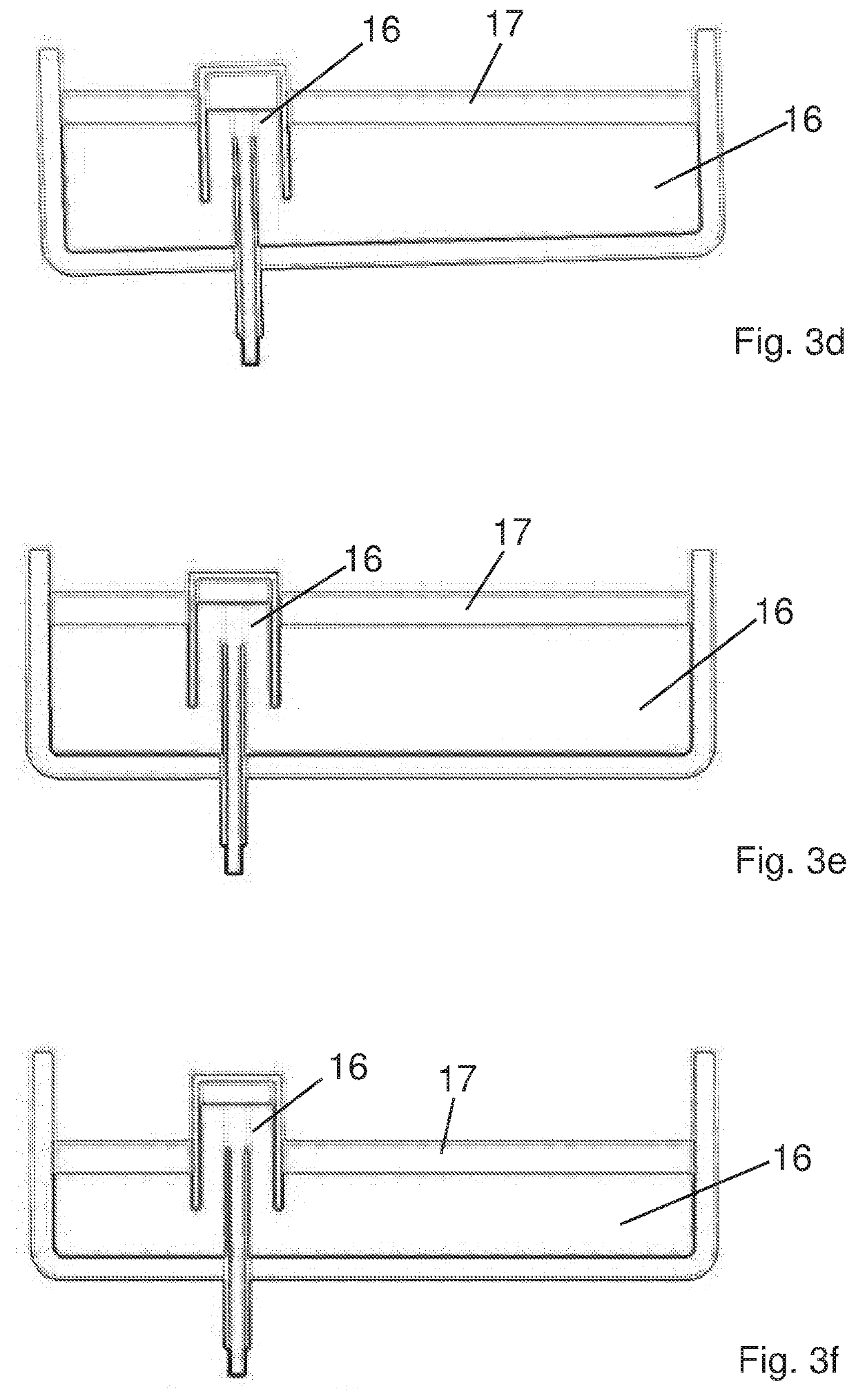
[0049]The figures show a melting furnace for metallurgical plant according to the invention.

[0050]The melting furnace is only partially shown in the figures and is represented as a whole by reference numeral 1. The melting furnace 1 is described only partially with particular reference to the elements which distinguish it from known furnaces. The parts of the furnace which are not described in detail herein should be understood as being in themselves known and conventional.

[0051]The melting furnace 1 of the invention comprises in all its embodiments:

[0052]a vessel having a bottom 2 which is part of the floor of the furnace and which comprises an inner surface adapted to be in contact with the metal mass or metal bath contained in the furnace 1;

[0053]a tapping duct 3 passing through the bottom 2;

[0054]rotation means to rotate the vesse...


PUM

PropertyMeasurementUnit
Angleaaaaaaaaaa
Distanceaaaaaaaaaa
Distanceaaaaaaaaaa

Abstract

A melting furnace for metallurgical plant comprising a vessel provided with a bottom; a tapping duct passing through the bottom; rotation means to rotate the vessel so that the tapping duct passes from a first reference position to a second position inclined with respect to said first reference position, and vice versa; wherein said tapping duct has a first stretch arranged in the thickness of the bottom and completely passing through the bottom, and a second stretch, adjacent to the first stretch, protruding inside the vessel; wherein there is provided a cover of the second stretch shaped as a tube closed at an upper end thereof and open at a lower end thereof; said tube being coaxial and spaced from said second stretch, and being spaced from a zone of the bottom which includes the first stretch of the tapping duct, whereby the cover, in cooperation with the second stretch of the tapping duct, acts as a tapping hood.

Description

CROSS-REFERENCE TO RELATED APPLICATIONS[0001]This application claims priority to PCT International Application No. PCT / IB2018 / 060090 filed on Dec. 14, 2018, which application claims priority to Italian Patent Application No. 102017000145098 filed on Dec. 15, 2017, the disclosures of which are expressly incorporated herein by reference.STATEMENT RE: FEDERALLY SPONSORED RESEARCH / DEVELOPMENT[0002]Not applicable.FIELD OF THE INVENTION[0003]The present invention relates to a melting furnace, e.g. an electric arc furnace, and operating method thereof, said melting furnace being used in a metallurgical plant.BACKGROUND ART[0004]The melting process conventionally envisages melting metal scrap by generating electric arcs, adapted to be sparked, in alternating current melting furnaces, between the electrodes arranged on the roof and the scrap, and adapted to be sparked, in direct current melting furnaces, between at least one electrode placed above (cathode) and at least a bottom electrode (a...

Claims


Application Information

Patent Timeline
IPC IPC(8): C21C5/46C21C5/52F27B3/19F27D3/15
CPCC21C5/4653C21C5/527F27B3/065F27D3/1509F27B3/19F27D3/1518
Inventor TERLICHER, STEFANOD'ODORICO, MATTIASANSA, MICHAEL
Owner DANIELI & C OFF MEC SPA
Why Eureka
Try Eureka