Lithium polymer battery cell

Inactive Publication Date: 2005-08-11
ENERDEL
View PDF2 Cites 16 Cited by
  • Summary
  • Abstract
  • Description
  • Claims
  • Application Information

AI Technical Summary

Benefits of technology

[0014] There is thus provided a lithium cell that provides good processing and performanc

Problems solved by technology

These plasticizers must be removed before the cell is activated with an electrolyte because, if mixed with the electrolyte, the plasticizers can damage the cell.
However, the electrodes cannot be directly cast onto the open structure materials, such that the electrode layers must be first cast onto a temporary substrate, such as mylar sheet, and

Method used


Image

  • Lithium polymer battery cell
  • Lithium polymer battery cell
  • Lithium polymer battery cell

Examples


Example

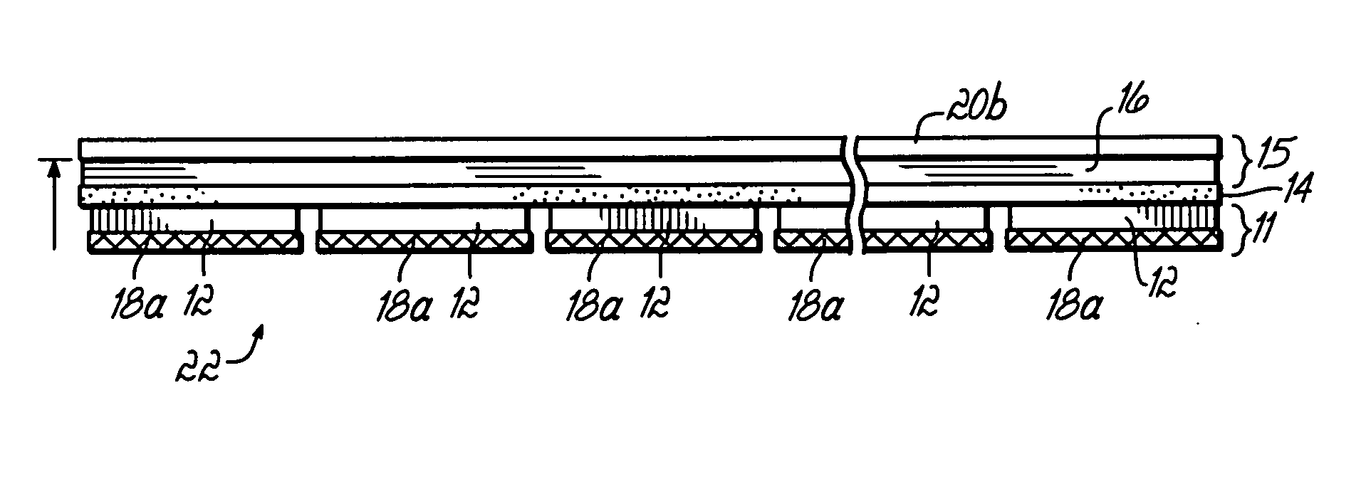
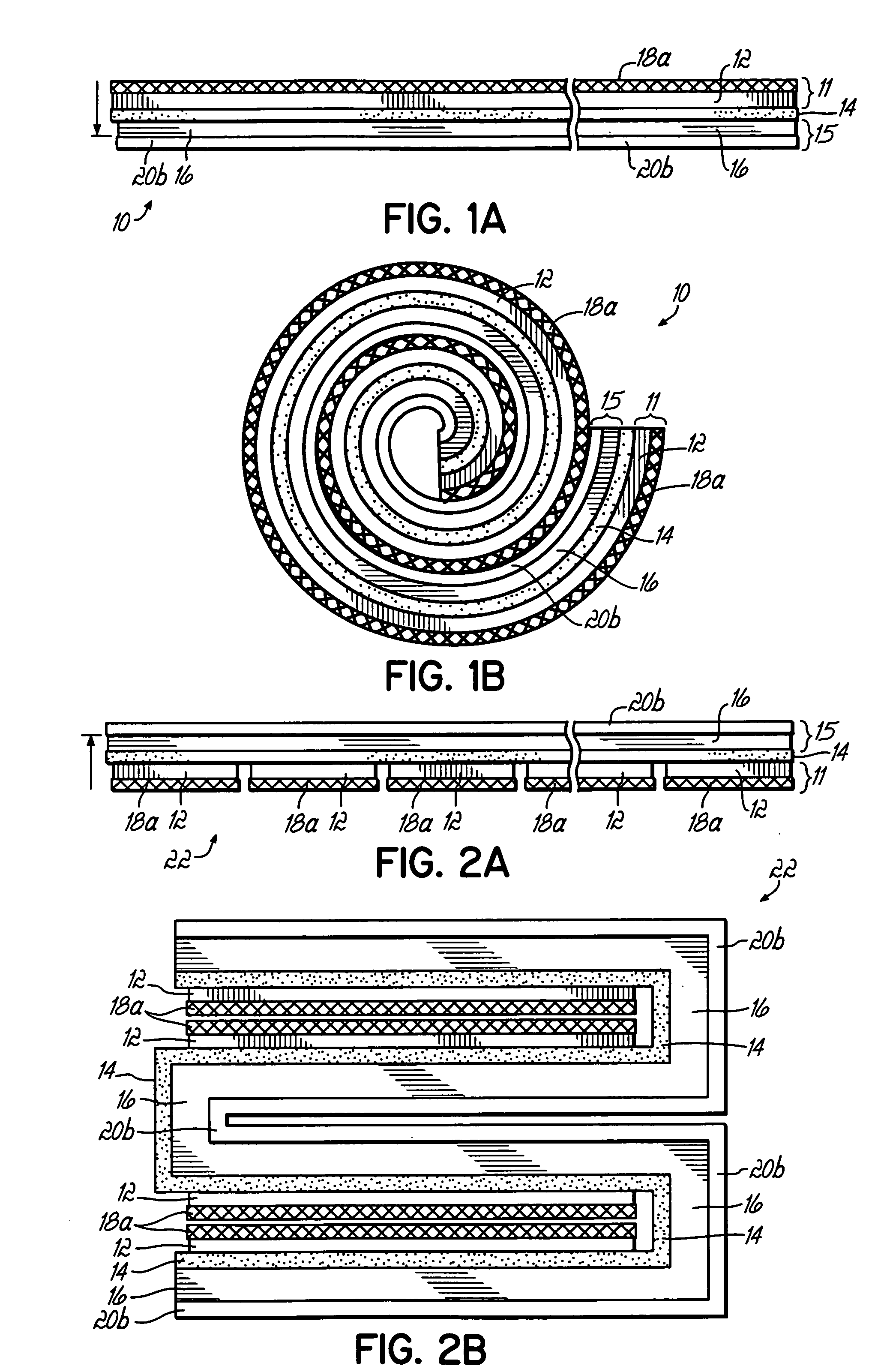
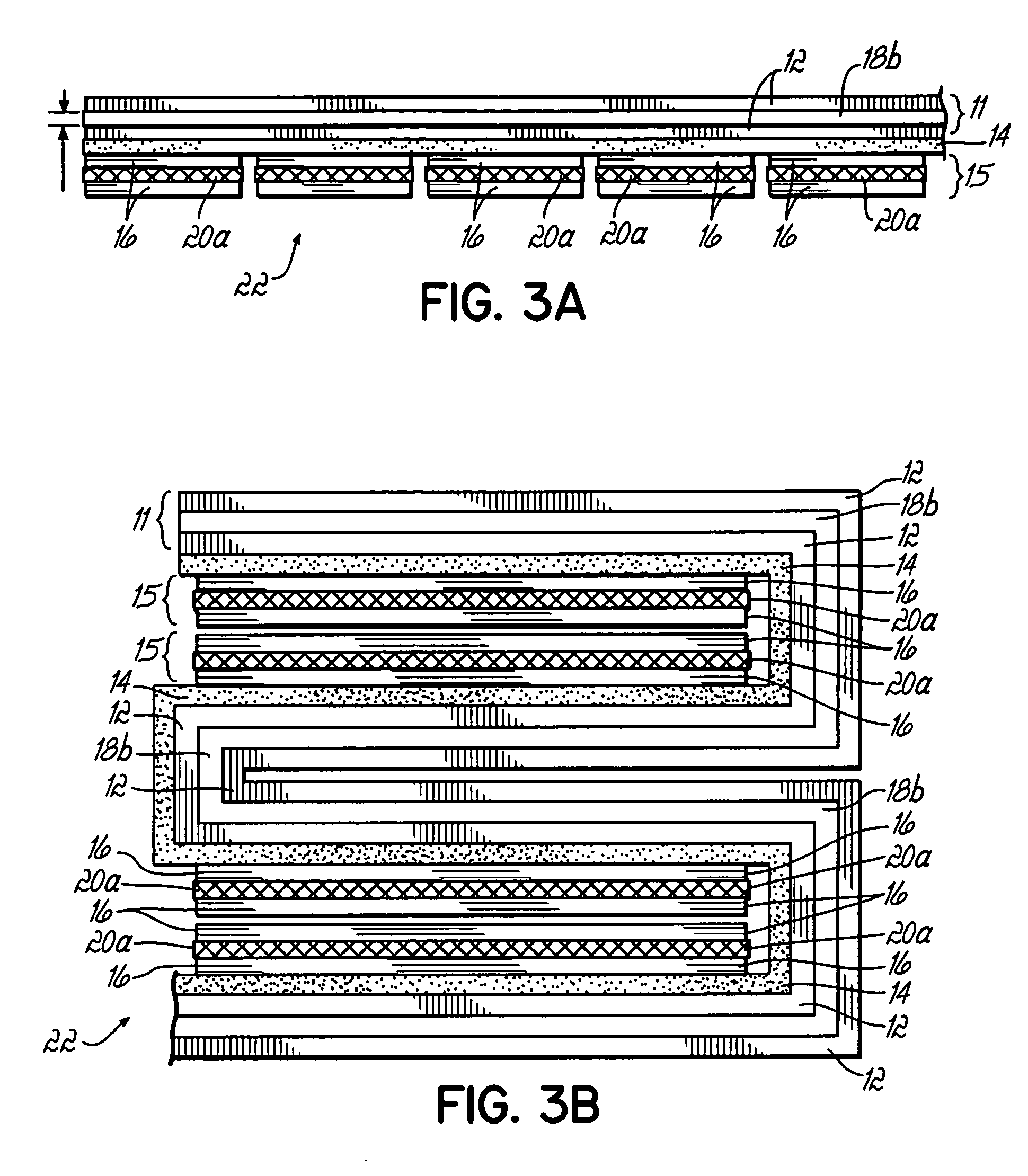
[0032] A battery cell of the present invention has two opposite electrodes, an anode (negative electrode) and cathode (positive electrode), with a separator between them. Each electrode (the anode and / or the cathode) may comprise two or more electrode layers that are separated by a current collector. For example, an anode may be comprised of two negative electrode layers separated by a negative current collector, and / or the cathode may be comprised of two positive electrode layers separated by a positive current collector. Alternatively, each electrode (the anode and / or the cathode) may comprise a single electrode layer and a current collector positioned external to the battery cell. The plane of the current collector is generally parallel to the plane of the polymer matrix film portion of the electrode. Similarly, the plane of separator films is generally parallel to the plane of the electrodes. In accordance with the present invention, one electrode comprises a metal grid current ...


PUM


Abstract

A lithium polymer battery cell configured with at least one anode and at least one cathode, each including a current collector, one of which is a metal foil and the other of which is a metal grid. The cell may be a unicell, bicell, multicell or a multibicell. In one example, the cell may include one or more anodes having a copper grid current collector and one or more cathodes having an aluminum foil current collector, and in another example, the cell may include one or more anodes having a copper foil current collector and one or more cathodes having an aluminum grid current collector.

Description

TECHNICAL FIELD [0001] This invention relates to laminate configurations for lithium cells, in particular lithium ion and lithium ion polymer battery cells. BACKGROUND OF THE INVENTION [0002] Lithium ion cells and batteries are secondary (i.e., rechargeable) energy storage devices well known in the art. The lithium ion cell, known also as a rocking chair type lithium ion battery, typically comprises essentially a carbonaceous anode (negative electrode) that is capable of intercalating lithium ions, a lithium-retentive cathode (positive electrode) that is also capable of intercalating lithium ions, and a non-aqueous, lithium ion conducting electrolyte therebetween. [0003] The carbon anode comprises any of the various types of carbon (e.g., graphite, coke, carbon fiber, etc.) which are capable of reversibly storing lithium species, and which are bonded to an electrochemically conductive current collector (e.g. copper foil or grid) by means of a suitable organic binder (e.g., polyvinyl...

Claims


Application Information

Patent Timeline
IPC IPC(8): H01M4/66H01M4/70H01M4/72H01M10/04H01M10/0525H01M10/0565H01M10/058H01M10/36H01M50/469
CPCH01M2/1673H01M2/18H01M4/661H01M4/70H01M4/72Y02E60/122H01M10/0431H01M10/0454H01M10/0525H01M10/0565H01M10/058H01M10/0413Y02E60/10H01M50/46Y02P70/50H01M50/469
Inventor PARSIAN, MOHAMMAD
Owner ENERDEL
Why Eureka
Try Eureka