Awning system

a technology of awnings and awning panels, which is applied in the field of awning systems, can solve the problems of increasing the cost of awning installation and causing a large amount of problems

Active Publication Date: 2020-08-04
LEWIS ANTONIO +1
View PDF22 Cites 1 Cited by
  • Summary
  • Abstract
  • Description
  • Claims
  • Application Information

AI Technical Summary

Problems solved by technology

This provides a considerable amount of problems and g

Method used


Image

  • Awning system
  • Awning system
  • Awning system

Examples


Embodiment Construction

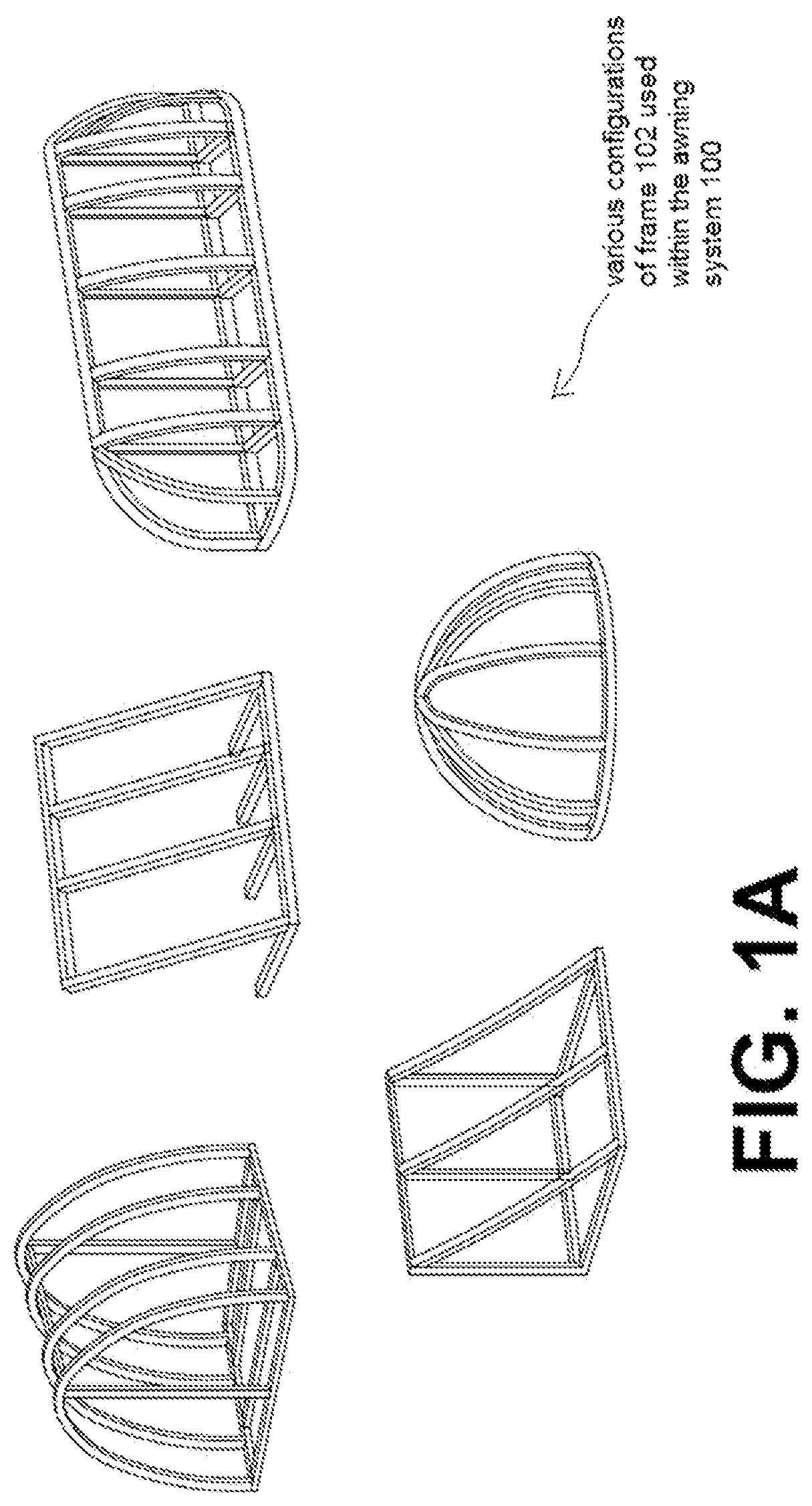
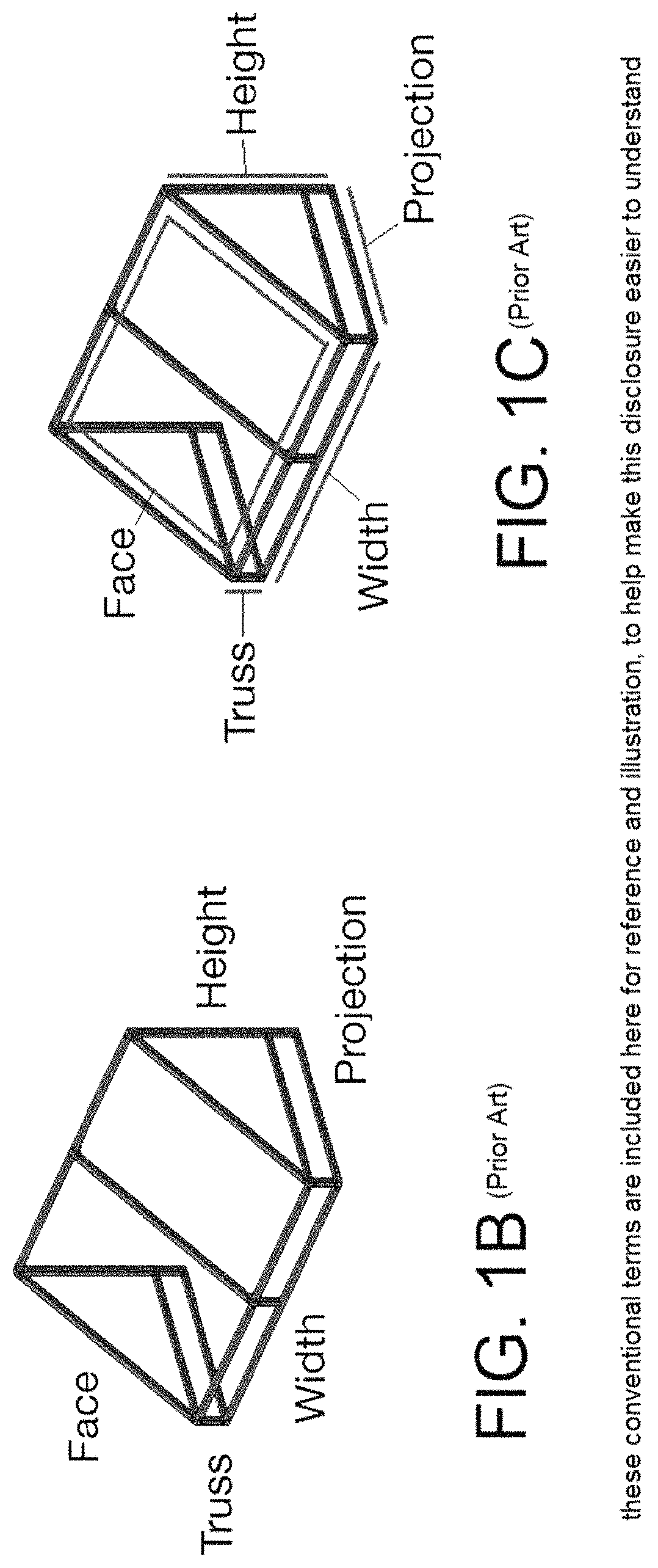
[0018]FIG. 1A shows some example frames 102 for use within the awning system 100. FIG. 1B (Prior Art) shows some conventional word-usage when referring to awnings in general, including face, truss, width, height, and projection or projection arms. FIG. 1B is included herein mainly to make this disclosure easier to understand.

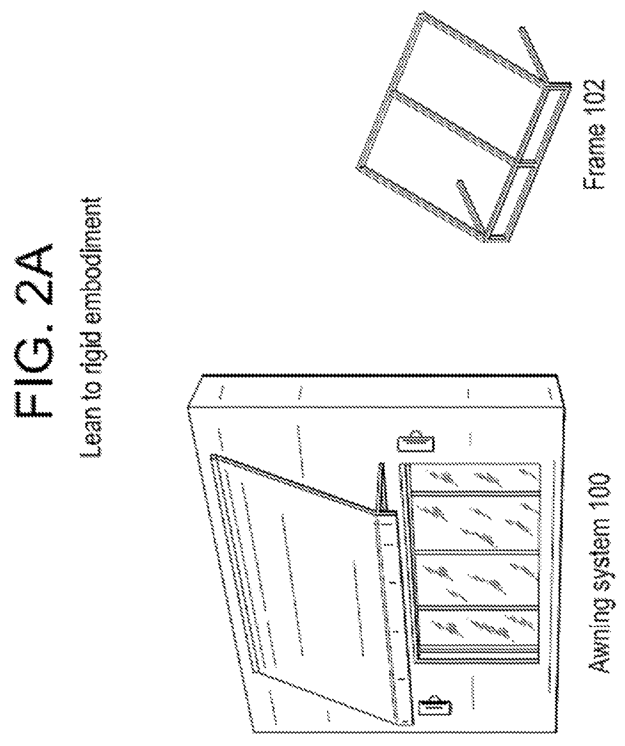
[0019]FIG. 2A shows a system 100 with a lean-to frame 102. FIG. 2B shows a system 100 with a lean-to rigid valence frame 102. FIG. 2C shows a system 100 with a standard frame 102. FIG. 2D shows a system 100 with a shed frame 102.

[0020]FIG. 3 shows details of an example awning system 100, using an interior view. As shown in FIG. 3, the miter connector 104 works with the Z-bracket 108 and the T-slot tubing 112. The specific frame 102 of the awning system 100 shown in FIG. 3 is a variation of the “lean to” frame 102 shown in FIG. 2A, except that in FIG. 3, the projection arms are not parallel with the ground. The Z-bracket 108 fits within a vertical portion of T-sl...


PUM


Abstract

An awning system having miter connectors suitable for attaching to portions of T-slot tubing members is disclosed. The awning system can be shipped by conventional shipping mechanisms, does not require welding, and does not require a flat-bed truck for transport. Also, the awning system can then be assembled and installed on-site, rather than being shipped in a fully pre-assembled state. The awning system uses proprietary tubing members and (in most embodiments) a miter connector to form an awning frame.

Description

BACKGROUND OF THE INVENTION[0001]Many types of awnings require being pre-assembled prior to shipping and installation. This provides a considerable amount of problems and greatly increases the expense of awning installations. Consequently it is desired to have an awning-assembly which can be shipped by conventional means, and then assembled and installed on-site, rather than being shipped in a pre-assembled state.BRIEF DESCRIPTION OF THE DRAWINGS[0002]FIG. 1A shows some example frames for use within an awning system;[0003]FIGS. 1B and 1C (Prior Art) shows some conventional word-usage when referring to awnings in general;[0004]FIG. 2A shows a system with a lean-to frame;[0005]FIG. 2B shows a system with a lean-to rigid valence frame;[0006]FIG. 2C shows a system with a standard frame;[0007]FIG. 2D shows a system with a shed frame;[0008]FIG. 3 shows details of an example awning system;[0009]FIG. 4A shows a prior art T-slot tubing;[0010]FIG. 4B shows an embodiment of proprietary T-slot ...

Claims


Application Information

Patent Timeline
IPC IPC(8): E04F10/04E04F10/02E04H15/34
CPCE04F10/04E04F10/02E04H15/34
Inventor LEWIS, ANTONIOLEWIS, CHRISTINE
Owner LEWIS ANTONIO
Why Eureka
Try Eureka