Open frame sight system

a sight system and open frame technology, applied in the field of reflex aiming devices, can solve the problems of increasing the possibility of the sight snagging on the holster, the overall height and profile of the sight remains rather tall, and the time to acquire the target in the sight may be limited, so as to quickly visualize and acquire the target, the overall height and profile of the sight can be reduced, and the effect of quick customization

Active Publication Date: 2020-08-04
GRACE ENG
View PDF6 Cites 2 Cited by
  • Summary
  • Abstract
  • Description
  • Claims
  • Application Information

AI Technical Summary

Benefits of technology

[0020]The current embodiments of the aiming device provide benefits in shooting sports and hunting that previously have been unachievable. For example, where the sight includes an open top of a protective frame, this construction allows a user to view more of a target as compared to conventional closed protective frames of reflex sights. Further, the present open protective frame enables a user to more quickly visualize and acquire the target because more of the target is viewable in the field of view of the optical element, particularly while centering the superimposed dot on the target. Where the optical element is removable and / or replaceable relative to the frame and sight in general, a user can quickly change out a scratched, chipped or otherwise compromised optical element. In addition, where the sight is provided with multiple different optical elements in a kit, a user can quickly customize their sight and use an optical element best suited for the application. In cases where the dot is displayed in the upper portion of the optical element, closer to the uppermost edge than to the lowermost edge of the optical element, the overall height and profile of the sight can be decreased as compared to conventional reflex sights having a red dot centered on a lens. In other words, such as a sight can eliminate the excess height of the lens common to prior sights having a red dot perfectly centered on a lens, for example, at the focal point of the lens.

Problems solved by technology

With most present technology, however, the profile of most reflex sights remains rather tall.
This can increase the possibility of the sight snagging on a holster, clothing or other elements in a shooting competition or during a hunting activity, when time to acquire a target in the sight may be limited.
In addition, most lenses of the above noted reflex sights are constructed from glass, which can be prone to being scratched.
Glass lenses also can be cracked or fractured if the firearm is dropped or inadvertently engaged with objects at the range or in the field.
Thus, the above reflex sights are circumferentiated with a protective frame to protect all the edges of the lens, and especially the top edge of the lens which sits highest on the sight, which means it is usually most prone to being bumped.
With the top frame guard being enlarged, and / or the upper rubber bumper being present, however, these components of the protective frame obscure a notable portion of a target when aiming the sight.
This can in some cases make target acquisition more difficult and time consuming.

Method used


Image

  • Open frame sight system
  • Open frame sight system
  • Open frame sight system

Examples


Embodiment Construction

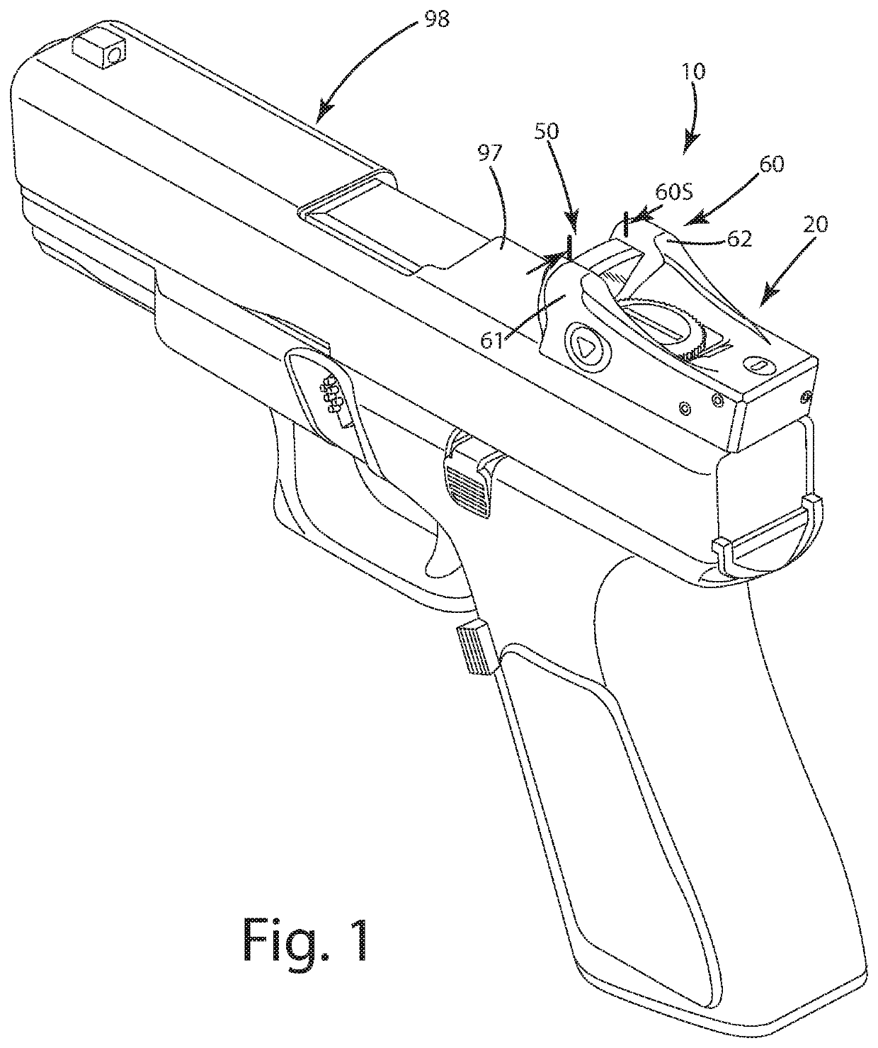
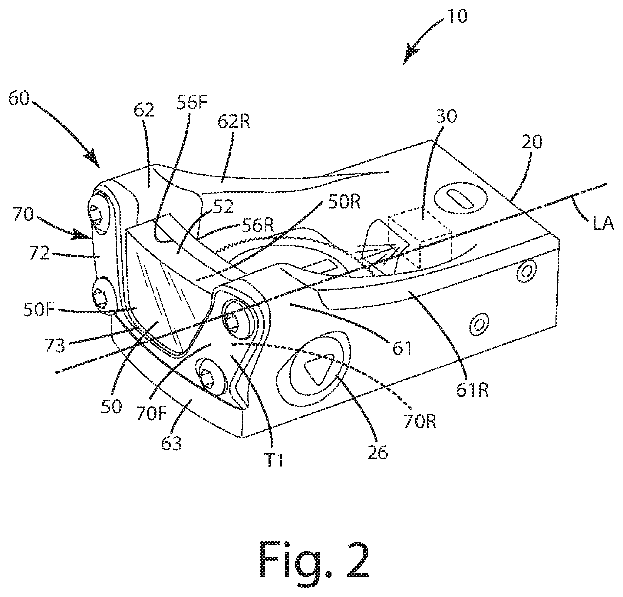
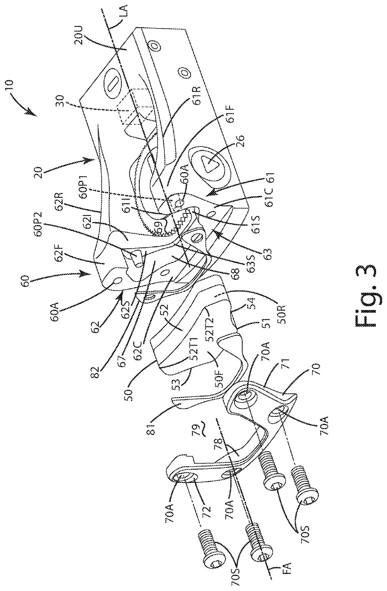
[0030]A current embodiment of the aiming system, also referred to as a sight herein, is illustrated in FIGS. 1-6 and generally designated 10. To begin, the sight 10 is shown mounted on a semi-automatic pistol. The sight 10 can, however, be mounted on other types of projectile shooting devices. For example, it can be mounted to other types of firearms, including but not limited to a rifle (for example, a long rifle, a carbine, an assault rifle, a bolt pump rifle or a battle rifle); a shotgun (of any gauge) and / or a machine gun (for example, a machine pistol, a light machine gun, a mini gun, a medium machine gun or a heavy machine gun). The firearm can include any type of action, for example, bolt action, lever action, pump action and / or break action. The firearm can be single shot, automatic and / or semiautomatic. Further optionally, the firearm can be in the form of a vehicle-mounted weapon, mounted directly to the vehicle, a watercraft or other mode of transportation of course. As u...


PUM


Abstract

An aiming device is provided including a body, an illumination device associated with the body and an optical element, where the illumination device is operable to selectively display a dot on the optical element being visible to a user. The optical element can include an upper edge and a lower edge, and the dot can display closer to the upper edge than to the lower edge, in some cases in the upper half or one third of the height of the optical element. The device can include a protective frame to which the optical element is joined, and the optical element upper edge can be unconcealed by any part of the protective frame above the upper edge, falling within an open top span of the frame. The optical element can be removable and replaceable relative to the protective frame, with a retainer plate temporarily securing the element to the frame.

Description

CROSS-REFERENCE TO RELATED APPLICATION[0001]This application claims benefit of U.S. Provisional Application (62 / 675,246), filed May 23, 2018 which is hereby incorporated by reference in its entirety.BACKGROUND OF THE INVENTION[0002]The present invention relates to aiming devices, and more particularly to reflex aiming devices having an increased field of view.[0003]The popularity and use of firearms for hunting, target shooting, and other dynamic shooting sports, has increased over the past several decades. The fast-paced, competitive nature of shooting and the desire by hunters to have well placed, ethical shots, have led to the development and commercialization of a variety of aiming devices. These devices include fiber optic sights, illuminated scope reticles and reflex sights, to name a few.[0004]Reflex sights typically are used with firearms in a variety of shooting sports and hunting activities where quick target acquisition is favorable. Such sights superimpose a bright illum...

Claims


Application Information

Patent Timeline
Patent Type & Authority Patents(United States)
IPC IPC(8): F41G1/14F41G1/06F41G1/34
CPCF41G1/065F41G1/14F41G1/345F41G1/30F41G1/17
Inventor GRACE, LOUISSCHULZ, CODY M.
Owner GRACE ENG
Why Eureka
Try Eureka