Bed bug detector system

a technology for detection systems and bugs, applied in fire alarms, substation equipment, instruments, etc., to achieve the effects of low manufacturing cost, convenient and efficient manufacturing and marketing, and durable and reliable construction

Active Publication Date: 2020-08-11
COGLEY THOMAS PAUL
View PDF115 Cites 4 Cited by
  • Summary
  • Abstract
  • Description
  • Claims
  • Application Information

AI Technical Summary

Benefits of technology

[0014]It is therefore an object of the present invention to provide a new and improved bed bug detector system which has all of the advantages of the prior art insect eliminating devices of known designs and configurations and none of the disadvantages.
[0015]It is another object of the present invention to provide a new and improved bed bug detector system which can be easily and efficiently manufactured and marketed.
[0016]It is a further object of the present invention to provide a new and improved bed bug detector system which is of durable and reliable constructions.
[0017]An even further object of the present invention is to provide a new and improved bed bug detector system which is susceptible of a low cost of manufacture with regard to both materials and labor, and which accordingly, is then susceptible of low prices of sale to the consuming public, thereby making such bed bug detector system economically available to the buying public.
[0018]Lastly, it is another object of the present invention to provide a bed bug detector system which can be used for attracting bed bugs, for killing the attracted bed bugs, and for maximizing bed bugs attracted and killed, in a safe, ecological, convenient, and economical manner.

Problems solved by technology

While these devices fulfill their respective, particular objectives and requirements, they do not describe a bed bug detector that is used to attract bed bugs and kill the attracted bed bugs, the attracting and killing being done in a safe, ecological, convenient, and economical manner,

Method used


Image

  • Bed bug detector system
  • Bed bug detector system
  • Bed bug detector system

Examples


Embodiment Construction

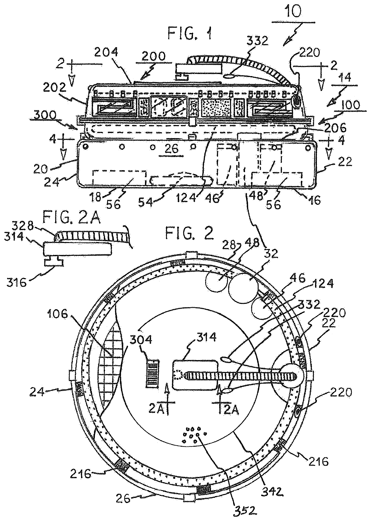
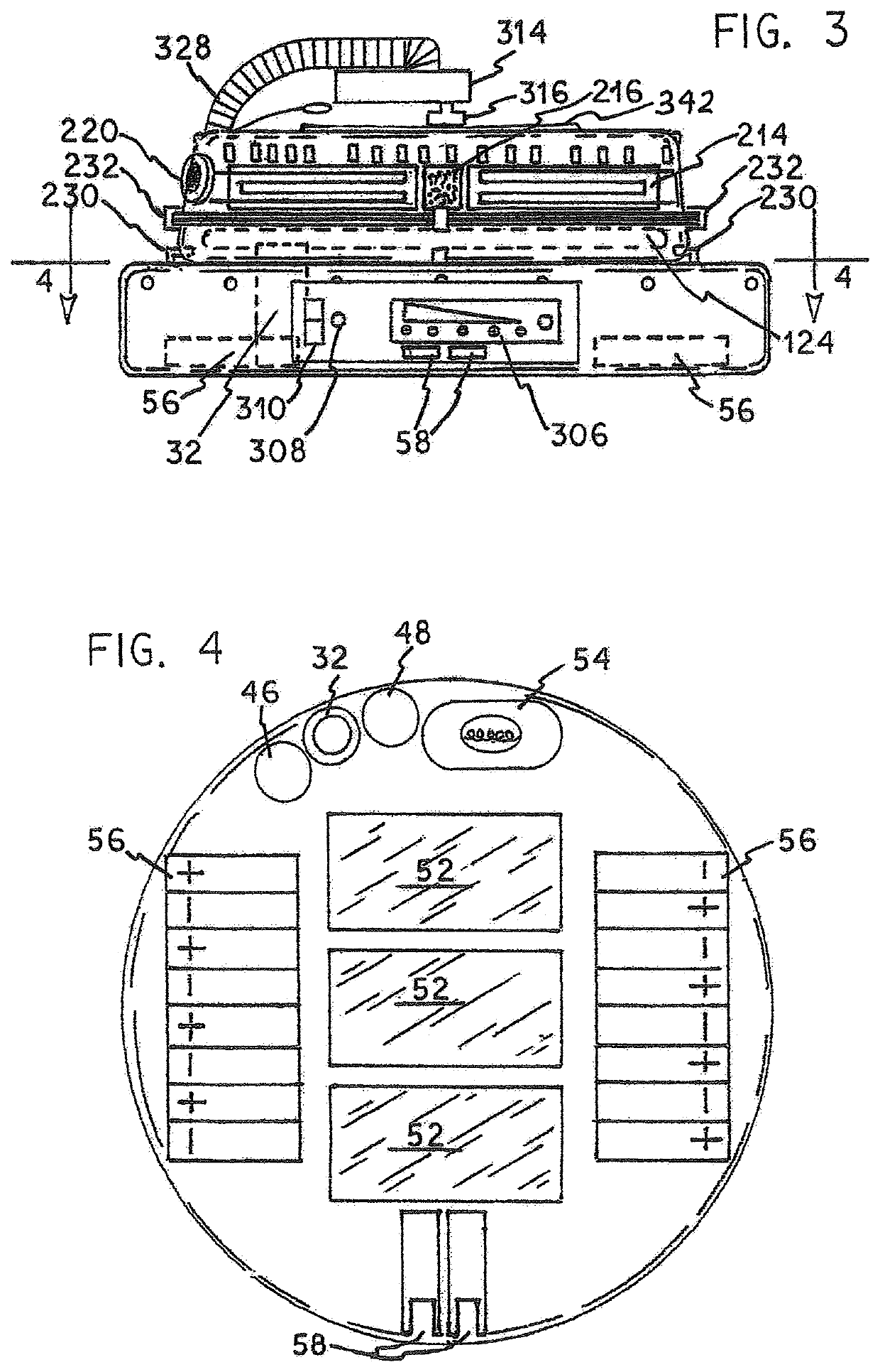
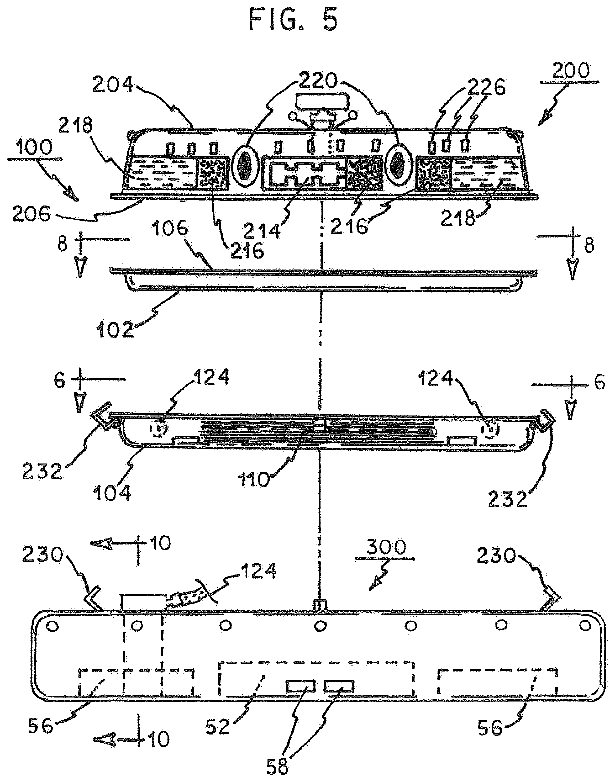
[0034]With reference now to the drawings, and in particular to FIG. 1 thereof, the preferred embodiment of the new and improved bed bug detector system embodying the principles and concepts of the present invention and generally designated by the reference numeral 10 will be described.

[0035]The present invention, the bed bug detector system is comprised of a plurality of components. Such components in their broadest context include an attracting assembly, a killing assembly, and a base assembly, as in my prior issued patent. In their broadest context the new features include an electric grid, a CO2 self-emitting device, a platform, a programmable computer chip, and a GPS transmitter.

[0036]From a specific viewpoint the present invention is the bed bug detector system of my prior patent with additional features. First provided is a base assembly 14. The base assembly has a base 16. The base has a circular floor 18 and a cylindrical side wall 20 and an open top forming a lower chamber....


PUM


Abstract

A bed bug attracting assembly is positioned at an upper location. A bed bug killing assembly is positioned at an intermediate location beneath the attracting assembly. A base assembly is positioned at a lower location beneath the killing assembly for maximizing the number of bed bugs attracted and killed. A control assembly has a user visible digital UPC code, a battery power percentage indicator with an ON / OFF button and a sound activated switch, a cell phone with a macro-lens, and two light emitting diode positioned adjacent thereto to illuminate bed bugs. An electric grid triggers a camera detector. A CO2 self-emitting device includes graphite and an electrical charge. A platform with pores holds a lure over a miniature fan. A programmable computer is preprogrammed to modulate attraction modalities. A GPS transmitter is activated to sent to receives to secure the area of infestation.

Description

RELATED APPLICATIONS[0001]The present application is based upon Provisional Application No. 62 / 771,799 filed Nov. 27, 2018, and Provisional Application No. 62 / 775,414 filed Dec. 5, 2018, the priority of which is claimed and is an improvement over my prior patent issued Oct. 9, 2018 as U.S. patent Ser. No. 10 / 091,980 which is a continuation-in-part of application Ser. No. 14 / 731,884 filed Jun. 5, 2015, now U.S. Pat. No. 10,021,871 issued Jul. 17, 2018, the subject matter of which applications is incorporated herein by reference.BACKGROUND OF THE INVENTIONField of the Invention[0002]The present invention relates to a bed bug detector system and more particularly pertains to attracting bed bugs and for killing the attracted bed bugs, the attracting and killing being done in a safe, ecological, convenient, and economical manner.Description of the Prior Art[0003]The use of insect eliminating devices of known designs and configurations is known in the prior art. More specifically, insect ...

Claims


Application Information

Patent Timeline
Patent Type & Authority Patents(United States)
IPC IPC(8): A01M1/02A01M1/10A01M1/14A01M1/22H04M1/215G08B19/00G08B17/10A01M1/04G01S19/42
CPCG08B17/10A01M1/026A01M1/103A01M1/023A01M1/04H04M1/215A01M1/223A01M1/145G08B19/00A01M2200/011H04M2250/52G01S19/42G08B17/00H04M1/04G01S19/14H04M1/72409Y02A50/30
Inventor COGLEY, THOMAS PAUL
Owner COGLEY THOMAS PAUL
Why Eureka
Try Eureka