Micromechanical spring for a sensor element

a sensor element and micromechanical technology, applied in the direction of speed/acceleration/shock measurement, flexible microstructural devices, instruments, etc., can solve the problems of wide production variation, virtually impossible to shift the interference mode without shifting the use mode, etc., and achieve the effect of advantageously minimizing the risk of breakage of the micromechanical spring

Active Publication Date: 2020-08-11
ROBERT BOSCH GMBH
View PDF9 Cites 1 Cited by
  • Summary
  • Abstract
  • Description
  • Claims
  • Application Information

AI Technical Summary

Benefits of technology

[0015]In this way, an added degree of freedom is advantageously provided for the micromechanical spring, in that a sensitivity with respect to interference mode is influenceable.
[0019]One advantageous refinement of the micromechanical spring is distinguished by the fact that the at least two spring sections are designed in such a way that in a frequency space a detection mode of the micromechanical spring is a defined distance apart from an interference mode of the micromechanical spring. This advantageously provides a desired insensitivity to the interference mode, which is advantageous for certain sensors. A mode-optimized spring design is implemented in this way, which effectuates favorable operating properties of the sensor element.
[0022]Another advantageous refinement of the micromechanical spring is characterized in that transition areas between the spring sections are formed with a defined rounding. In this way, it is facilitated that a risk of breakage for the micromechanical spring is advantageously minimized.
[0023]Another advantageous refinement of the micromechanical spring is characterized in that the micromechanical spring is integrally formed with a rocker element of the sensor element. In this way, it is possible to use proven micromechanical manufacturing processes for manufacturing the micromechanical spring.

Problems solved by technology

Thus, shifting the interference mode without shifting the use mode and vice versa is virtually impossible.
A present approach to this problem is to use very short and very thin micromechanical springs, which inevitably results in a wide production variation (strongly dependent on an edge loss, i.e., deviations of actually produced dimensions as opposed to planned dimensions due to production tolerances).

Method used


Image

  • Micromechanical spring for a sensor element
  • Micromechanical spring for a sensor element
  • Micromechanical spring for a sensor element

Examples


Embodiment Construction

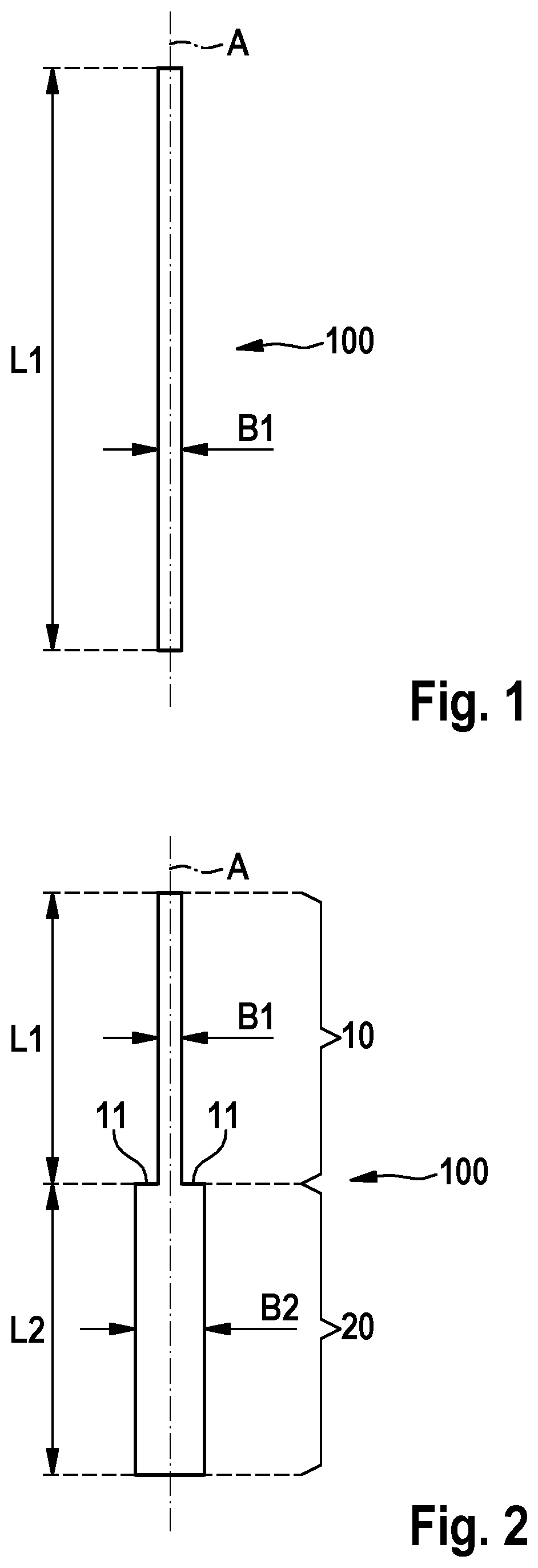
[0032]An example embodiment of the present invention provides a micromechanical spring for a sensor element, which includes an expanded degree of design freedom with respect to a specific operating characteristic in the form of an interference mode. In this way, it is possible to advantageously influence both the detection mode as well as the interference mode of the micromechanical spring, as a result of which an operating behavior of the sensor element including the micromechanical spring may be designed according to specifications.

[0033]Detection mode (use mode) and interference mode are understood below to mean frequencies or frequency ranges in a frequency space, which define frequencies for an intended excitation (detection mode) or an unintended excitation (interference mode) of mechanical spring 100. The two cited modes in this case represent a first mode and a second mode, there actually being an infinite number of modes available which, with increasing number of modes, req...


PUM


Abstract

A micromechanical spring for a sensor element, including at least two spring sections formed along a sensing axis, the at least two spring sections each having a defined length, and the at least two spring sections having different defined widths.

Description

CROSS REFERENCE[0001]The present application claims the benefit under 35 U.S.C. § 119 of German Patent Application No. DE 102016220507.2 filed on Oct. 19, 2016, which is expressly incorporated herein by reference in its entirety.FIELD[0002]The present invention relates to a micromechanical spring for a sensor element. The present invention also relates to a method for manufacturing a micromechanical spring for a sensor element.BACKGROUND INFORMATION[0003]Torsion springs are presently designed in z-acceleration sensors and xz-acceleration sensors (as a rotatable rocker) either having a simple beam, a length and a width being used as a degree of design freedom, or as a conductor spring (two longitudinal beams connected by cross beams) if, in addition to the usual requirements (requirements relating to detection sensitivity, etc.) vibration requirements must also be met.[0004]In the case of a simple beam, the required use mode (detection mode) is adjusted by a length and a width, which...

Claims


Application Information

Patent Timeline
Patent Type & Authority Patents(United States)
IPC IPC(8): G01P15/08G01P15/03
CPCG01P15/0802G01P15/032G01P15/08G01P2015/0828B81B2203/0154G01P2015/0851B81B3/0027B81C1/0019B81B2201/0228
Inventor KOSTER, MONIKAEID, RUDY
Owner ROBERT BOSCH GMBH
Why Eureka
Try Eureka