
Position input system and method

a technology of input system and position, applied in the field of touch screen, can solve problems such as permanent damage to the touch screen, and achieve the effect of enhancing the reliability and lifetime of the touch screen of the position input system

Active Publication Date: 2020-08-11
HIMAX TECH LTD
View PDF6 Cites 6 Cited by
  • Summary
  • Abstract
  • Description
  • Claims
  • Application Information

AI Technical Summary

Benefits of technology

The present invention aims to provide a position input system and method that can overcome the burn-in or image sticking problem and enhance the reliability and lifetime of the touch screen.

Problems solved by technology

Unfortunately, the burn-in or image sticking problem may cause permanent damage to the touch screen.

Method used


Image

  • Position input system and method
  • Position input system and method
  • Position input system and method

Examples


first embodiment

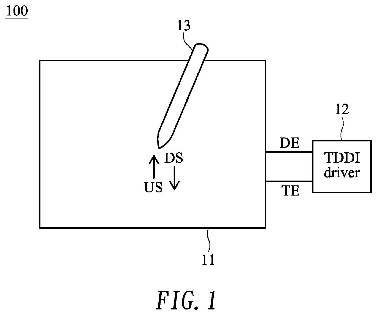
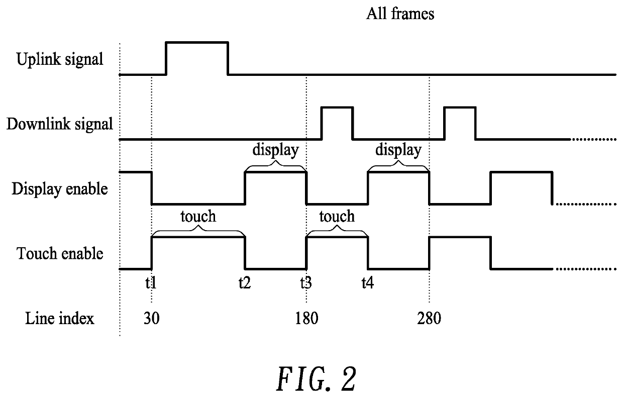
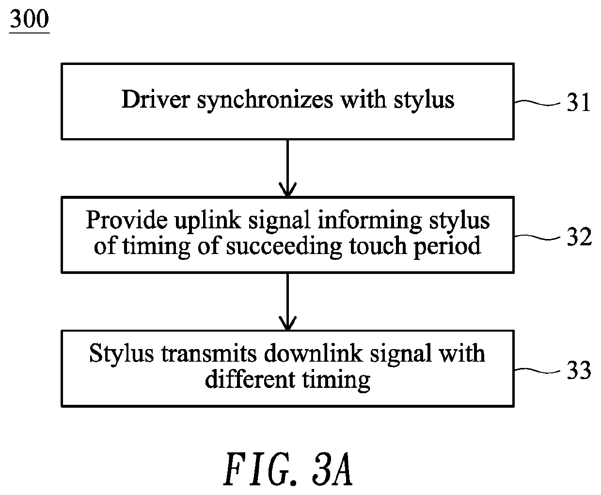
[0019]FIG. 3A shows a flow diagram illustrating a position input method 300 capable of overcoming the burn-in or image sticking problem according to the present invention. The position input method 300 of FIG. 3A may be adaptable to the position input system 100 of FIG. 1. FIG. 3B shows a timing diagram exemplifying pertinent signals of the position input system 100 of FIG. 1 performed according to the position input method 300 of FIG. 3A.

[0020]In step 31, in a touch period t1-t2 (when the touch enable signal TE is asserted), the TDDI driver 12 transmits an uplink signal US to and synchronizes with the active stylus 13. According to one aspect of the embodiment, in step 32, the uplink signal US provided by the TDDI driver 12 may further contain timing information that informs the active stylus 13 of timing of a succeeding touch period (that is, time at which the succeeding touch period will happen). As exemplified in FIG. 3B, the uplink signal US provided by the TDDI driver 12 in th...

second embodiment

[0022]FIG. 4A shows a flow diagram illustrating a position input method 400 capable of overcoming the burn-in or image sticking problem according to the present invention. The position input method 400 of FIG. 4A may be adaptable to the position input system 100 of FIG. 1. FIG. 4B shows a timing diagram exemplifying pertinent signals of the position input system 100 of FIG. 1 performed according to the position input method 400 of FIG. 4A.

[0023]In step 41, in a touch period t1′-t2′ (when the touch enable signal TE is asserted), the TDDI driver 12 transmits an uplink signal US to the active stylus 13 via the touch screen 11. According to one aspect of the embodiment, the TDDI driver 12 changes (e.g., delays) timing of the touch period t1′-t2′ in the current frame N compared to the corresponding touch period t1-t2 in the previous frame N−1. As a result as exemplified in FIG. 4B, the uplink signal US is thus delayed with d2 compared to the previous frame N−1. The shifted time d2 for ea...


PUM


Abstract

A position input system includes a touch screen, an active stylus and a driver. The driver transmits an uplink signal to the active stylus via the touch screen in a current touch period, the uplink signal containing timing information that informs the active stylus of timing of a next touch period in which the active stylus transmits a downlink signal to the driver via the touch screen. In another embodiment, the driver transmits an uplink signal to the active stylus via the touch screen in a current touch period of a current frame at a time different from a corresponding touch period of a previous frame.

Description

BACKGROUND OF THE INVENTION1. Field of the Invention[0001]The present invention generally relates to a touch screen, and more particularly to a position input system and method capable of overcoming the burn-in problem.2. Description of Related Art[0002]A touch screen is an input / output device that adopts both touch technology and display technology in a single device and has been commonly adapted to electronic devices such as smart phones or tablet computers. The touch screen enables the user to interact directly with what is displayed.[0003]The touch screen ordinarily includes a display driver configured to perform display task and a touch driver configured to perform touch task. A touch with display driver integration (TDDI) driver has been recently proposed to integrate and manufacture the touch driver and the display driver in a single chip, thereby simplifying manufacturing, reducing cost and enhancing reliability.[0004]A stylus, particularly active stylus (or active pen), may...

Claims


Application Information

Patent Timeline
Patent Type & Authority Patents(United States)
IPC IPC(8): G06F3/041G09G5/00G06F3/038G06F3/0354
CPCG06F3/0412G06F3/04162G06F3/03545G09G5/003G06F3/038G06F2203/0384G09G2320/0257G06F3/0383G09G3/20G09G2300/0408G09G2310/08G06F3/04184G06F3/0442
Inventor LIN, CHANG-HUILIN, YU-CHUNCHANG, YAW-GUANG
Owner HIMAX TECH LTD
Learn More