Eureka AIR delivers breakthrough ideas for toughest innovation challenges, trusted by R&D personnel around the world.

Self-regulating current circuit apparatus and method

a current circuit and self-regulating technology, applied in the direction of electric variable regulation, process and machine control, instruments, etc., can solve the problems of deployment failure, release mechanism often adds significant development cost, and complexity and functionality in a small package, and achieves simple, reliable, and reliable

Active Publication Date: 2020-08-11
NASA
View PDF11 Cites 2 Cited by
  • Summary
  • Abstract
  • Description
  • Claims
  • Application Information

AI Technical Summary

Benefits of technology

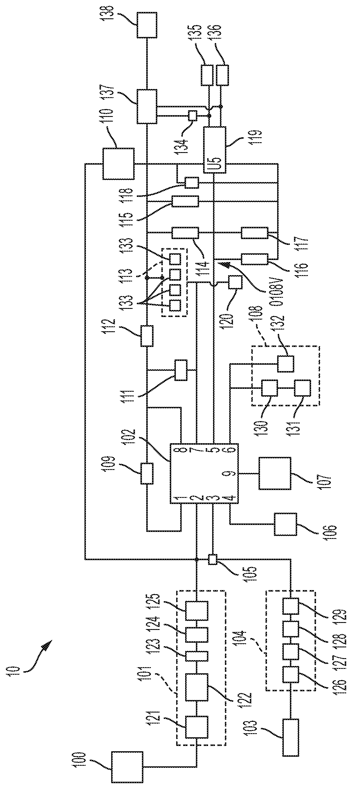
The present invention is about a small, reliable, and affordable circuit that can provide a constant current output for various applications such as airborne and space environments. The circuit includes a current source and a self-regulating circuit that uses a feedback mechanism and a high-side current sensor to maintain the desired current output. The circuit can be easily adjusted for different deployment devices by adjusting the gain of an operational amplifier. The technical effect of this invention is to provide a reliable and efficient power conversion solution in a compact package for various applications.

Problems solved by technology

This ever-increasing complexity and functionality in a small package require numerous mechanisms and deployables in order to meet space mission requirements.
Release mechanisms often add significant development costs to a satellite program and in the world of small satellites, such as CubeSats, the need for simple, reliable, and inexpensive release devices can be very important.
If too much current is applied, the wire could disintegrate, but if too little current is applied, there may not be enough heat to active the device; both situations resulting in deployment failure.

Method used


Image

  • Self-regulating current circuit apparatus and method

Examples


Embodiment Construction

[0041]The present invention is directed to an apparatus and method of a Self-Regulating Current Circuit having a small, robust footprint that will integrate a constant current source need for simple, reliable, and inexpensive release devices in airborne and other environments, including satellite deployment devices and pyrotechnic applications.

[0042]In one embodiment, the apparatus of the present invention includes a Self-Regulating Current Circuit (SRC2), which is a current circuit which utilizes a Switching Regulator to provide high efficiency power conversion and a high-side current monitor, but instead of driving the feedback input with a voltage divider to set the output voltage, in one embodiment, the Self-Regulating Current Circuit (SRC2) utilizes a high-side current sense resistor with an Operational Amplifier optimized for current sensing, to drive the feedback input to the Switching Regulator, thereby creating a Self-Regulating constant current source. By adjusting the gai...


PUM


Abstract

The present invention relates to an apparatus including a self-regulating current source, which utilizes a switching regulator to provide high efficiency power conversion and a high-side current monitor, but instead of driving the feedback input with a voltage divider to set the output voltage, the self-regulating current source utilizes a high-side current sense resistor with an operational amplifier optimized for current sensing, to drive the feedback input to the switching regulator, thereby creating a self-regulating constant current source. By adjusting the gain of the operational amplifier, the user can directly set the optimized current needed for using the apparatus in a variety of deployment devices, including satellite and pyrotechnic applications.

Description

ORIGIN OF THE INVENTION[0001]The invention described herein was at least in-part made by an employee of the United States Government and may be manufactured or used by or for the Government of the United States of American for governmental purposes without the payment of any royalties thereon or therefor.BACKGROUND OF THE INVENTION1. Field of the Invention[0002]The present invention relates to an apparatus and method of a Self-Regulating Current Circuit used in a variety of environments and applications, including satellite deployment devices and pyrotechnic applications.2. Description of the Related Art[0003]The need for simple, reliable, and inexpensive release devices can be important to the success of a variety of fields, including satellite deployment devices and pyrotechnic applications. In particular, the ability for a single mechanism to accomplish many of these releases is a desirable trait among CubeSat users. Whether the mechanism is used to release antennas, solar arrays...

Claims


Application Information

Patent Timeline
Patent Type & Authority Patents(United States)
IPC IPC(8): H02M3/156H02M3/158B64G1/64H02M3/04H02M1/44H02M1/00F42B3/10
CPCH02M1/44H02M3/04B64G1/645F42B3/10H02M2001/0009H02M3/156F42C19/12B64G1/428H02M1/0003B64G1/6455H02M1/0009
Inventor HESH, SCOTT V.MAHON, MICHAEL J.
Owner NASA
Why Eureka
Eureka Blog
Learn More