Optical module for multi-wavelength

a technology of optical modules and multi-wavelengths, applied in the field of optical communication elements, can solve the problems of increasing manufacturing costs and difficulty in mass production of optical modules b>100/b>, and achieve the effect of easy mass production fabrication

Inactive Publication Date: 2006-06-29
SAMSUNG ELECTRONICS CO LTD
View PDF9 Cites 7 Cited by
  • Summary
  • Abstract
  • Description
  • Claims
  • Application Information

AI Technical Summary

Benefits of technology

[0012] Accordingly, the present invention has been made to solve the above-mentioned problems occurring in the prior ar

Problems solved by technology

However, since the structure of the conventional optical module 100 is complicated, it is difficult to fabricate the optical module 100 in mas

Method used


Image

  • Optical module for multi-wavelength
  • Optical module for multi-wavelength
  • Optical module for multi-wavelength

Examples


Embodiment Construction

[0024] Hereinafter, embodiments of the present invention will be described with reference to the accompanying drawings. For the purposes of clarity and simplicity, a detailed description of known functions and configurations incorporated herein will be omitted as it may make the subject matter of the present invention unclear.

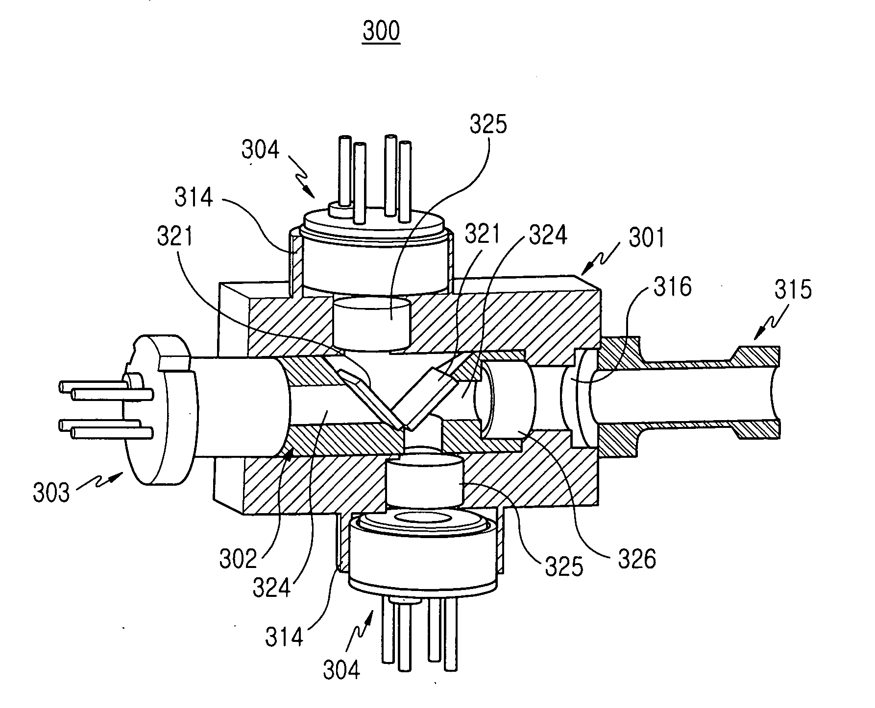
[0025]FIG. 4 is a perspective view illustrating the structure of an optical module for a multi-wavelength according to one embodiment of the present invention. As shown, the optical module 300 according to the present invention includes a module body 301, in which a laser diode 303, photo diodes 304 and an optical fiber 315 are installed thereon, and a filter holder 302 inserted into the module 301.

[0026] Referring to FIGS. 5 and 6, the module body 301 has a receiving hole 311 extending lengthwise from one end of the module body 301 and a stepped portion 313 formed at another end of the receiving hole 311. A connection hole 316 connected to an optical fiber i...


PUM


Abstract

An optical module includes a module body on which at least one photo diode is mounted, a filter holder inserted into the module body, and a thin film filter mounted on the filter holder in order to guide optical signals towards photo diodes in such a manner that optical signals with corresponding wavelengths are received in the photo diodes. The filter holder, on which the thin film filters are mounted, is fabricated separately from the module body and houses active elements, such as the laser diode and photo diodes. The filter holder is inserted into the module body thereafter, so the optical module is easily fabricated at a low cost and in a simple manner.

Description

CLAIM OF PRIORITY [0001] This application claims priority to an application entitled “Optical Module For Multi-Wavelength,” filed with the Korean Intellectual Property Office on Dec. 28, 2004 and assigned Ser. No. 2004-113737, the entire contents of which are incorporated herein by reference. BACKGROUND OF THE INVENTION [0002] 1. Field of the Invention [0003] The present invention relates to an optical communication element. More particularly, the present invention relates to an optical module for housing a plurality of active elements, such as a laser diode and a photo diode. [0004] 2. Description of the Related Art [0005] In general, an optical module includes an electric circuit device, such as a printed circuit board, on which a laser diode, a photo diode, etc., are mounted. The optical module outputs an electric signal by converting a radio frequency signal into an optical signal or vice versa. As the information industry has progressed rapidly, a great amount of information is...

Claims


Application Information

Patent Timeline
IPC IPC(8): G02B6/36H01L31/10H01S5/022
CPCG02B6/29362G02B6/4214G02B6/4246G02B6/42
Inventor PARK, JOONG-WANPARK, MUN-KUEBAEK, JAE-MYUNG
Owner SAMSUNG ELECTRONICS CO LTD
Why Eureka
Try Eureka