Antitheft and monitoring system for photovoltaic panels

a monitoring system and photovoltaic panel technology, applied in the direction of burglar alarm mechanical actuation, burglar alarm by hand-portable object removal, instruments, etc., can solve the problem of high risk of photovoltaic panel th

Inactive Publication Date: 2010-10-07
SAVIO SPA
View PDF6 Cites 6 Cited by
  • Summary
  • Abstract
  • Description
  • Claims
  • Application Information

AI Technical Summary

Benefits of technology

[0011]The present invention advantageously exploits the characteristics of the antitheft device to provide also the monitoring function. In this way, i.e., re-using the hardware already installed, the possibility of performing the operations of monitoring and diagnostics is achieved without requiring installation of a dedicated system.
[0012]The antitheft device can be applied to any photovoltaic panel, for example during its processing step (lamination), and this excludes any possibility of tampering with or removal of the antitheft device, without damaging the photovoltaic panel irreparably.
[0013]As will emerge clearly from the ensuing description, by appropriately managing an antitheft system that inhibits operation of the panels in the absence of an activation code it is possible to carry out monitoring of a photovoltaic field.
[0014]One of the main characteristics of the present invention lies precisely in the combination of the functions of antitheft device and monitoring system. Said functions use the same hardware as regards the panels and centralized hardware for the monitoring, which is in turn used for driving the inverter that connects the field of photovoltaic panels to the electric-power mains. The monitoring hardware could also have on board a GPS system for preventing theft of the panels that are combined to the inverter.

Problems solved by technology

However, since they are in the majority of cases sites that are not presided over, they are exposed to a high risk of theft of the photovoltaic panels.

Method used


Image

  • Antitheft and monitoring system for photovoltaic panels
  • Antitheft and monitoring system for photovoltaic panels
  • Antitheft and monitoring system for photovoltaic panels

Examples


Embodiment Construction

[0023]Described in detail in the first part of the description is operation of the antitheft device. Described, instead, in the second part of the description is operation of the monitoring system that uses the aforesaid antitheft device for the purposes of diagnostics of the individual panels that make up the photovoltaic plant.

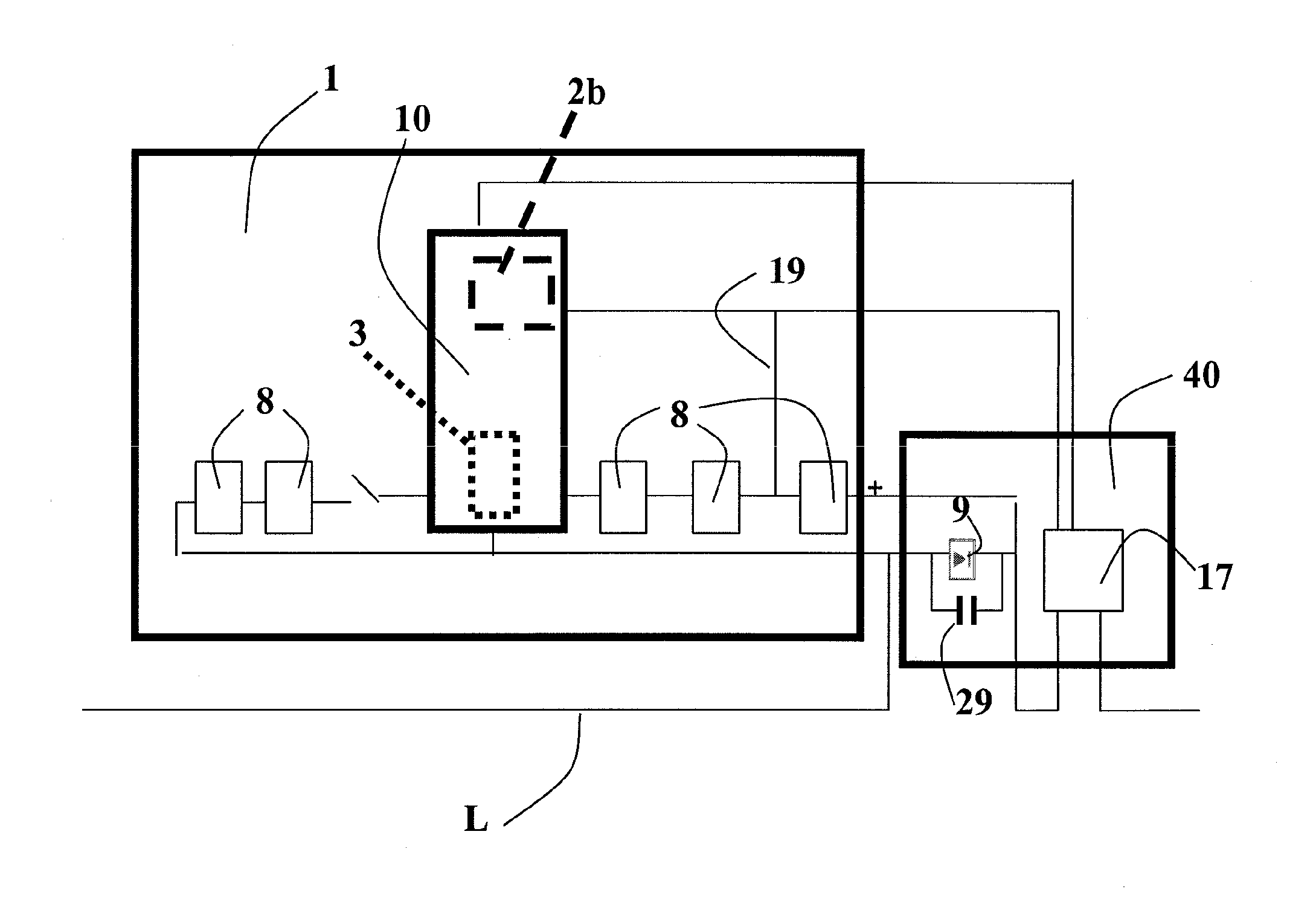
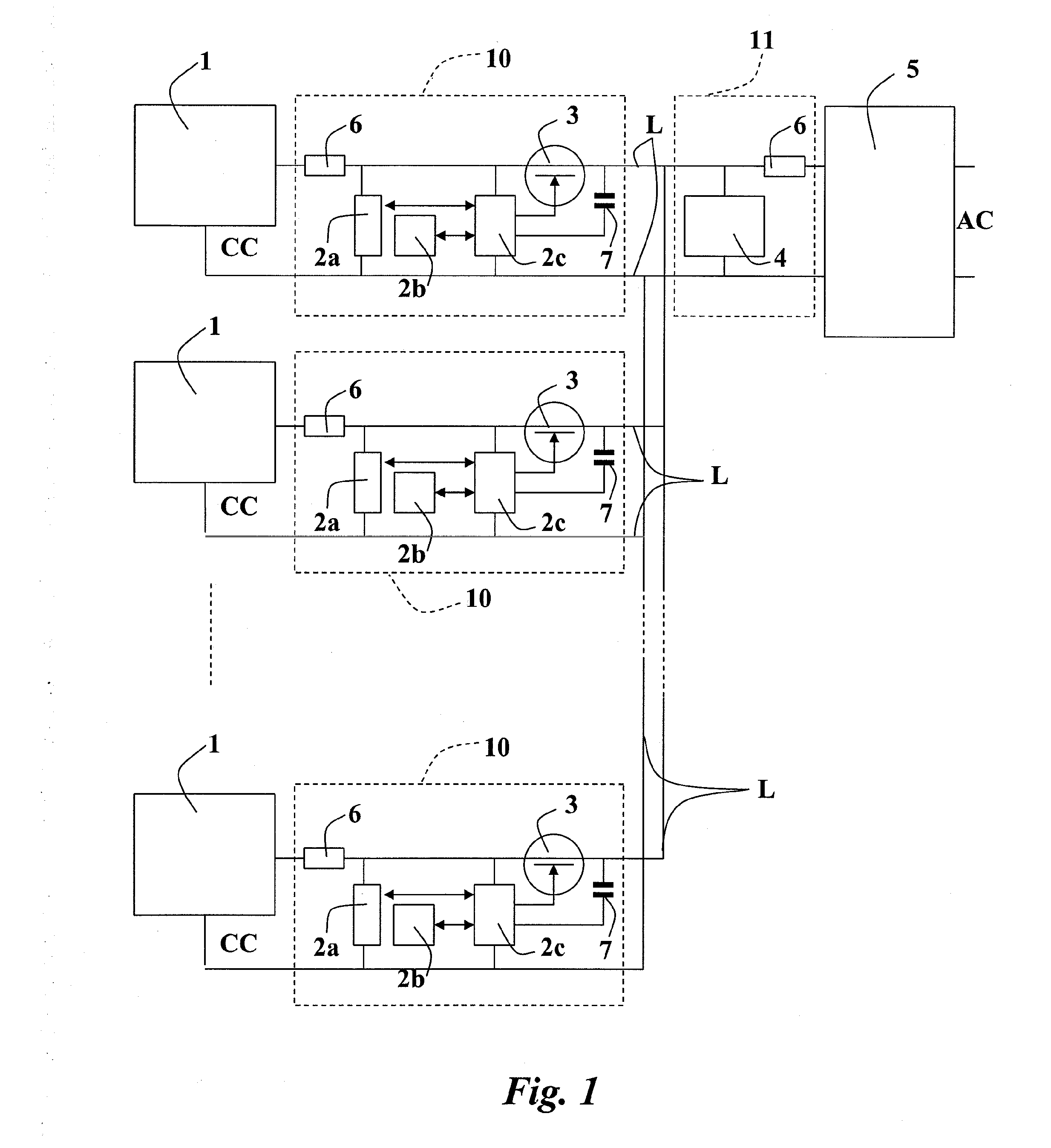
[0024]With reference to FIG. 1, an antitheft device for photovoltaic panels 1 connected by means of a connection line L to a distribution substation 5 comprises a first unit 11, associated to the distribution substation 5, and a plurality of second units 10, associated to the panels 1. The first unit 11 is designed to generate an activation code 4 and each of the second units 10 is designed to inhibit operation of the respective panel 1 in the absence of the activation code 4.

[0025]Once again with reference to FIG. 1, a plurality of photovoltaic panels 1 are connected in parallel to the two conductors of a connection line, designated as a whole by L, to form...


PUM


Abstract

An antitheft and monitoring system for a plurality of photovoltaic panels, wherein the panels are connected by means of a connection line to a distribution substation. The monitoring system comprises a first unit associated to the distribution substation, wherein the first unit is designed to generate activation codes, and a plurality of second units associated to the panels, wherein each of the second units is designed to inhibit operation of the respective panel in the absence of the activation code for a pre-set period. Furthermore, each second unit is selectively activatable via a unique activation code generated by the first unit. The antitheft and monitoring system is moreover configured to activate an individual panel selectively by sending onto the connection line the corresponding unique activation code and detecting, via a measuring device, the characteristics of voltage and current of the individual active panel.

Description

CROSS-REFERENCE TO RELATED APPLICATIONS[0001]This application claims benefit of European patent application number 09157373.3, filed Apr. 6, 2009, which is herein incorporated by reference.BACKGROUND OF THE INVENTION[0002]1. Field of the Invention[0003]The present invention relates to an antitheft and monitoring system for photovoltaic panels.[0004]2. Description of the Related Art[0005]Photovoltaic technology has witnessed a considerable expansion in the last few years; in particular, it is very advantageous in remote areas, where said technology has always occupied a strategic role for the distributed generation of electrical energy. However, since they are in the majority of cases sites that are not presided over, they are exposed to a high risk of theft of the photovoltaic panels.[0006]The idea of providing an antitheft system that will prevent operation of the photovoltaic panel when this is detached from the supply line is known, for example, from the international patent appl...

Claims


Application Information

Patent Timeline
Patent Type & Authority Applications(United States)
IPC IPC(8): G08B13/14
CPCG08B13/1418H01L31/02021Y02E10/50H01L31/042H02S50/00
Inventor BALBO DI VINADIO, AIMONEPALAZZETTI, MARIO
Owner SAVIO SPA
Why Eureka
Try Eureka