Pulse generation module, and optical communication transmitter system and non-linear equalizing method thereof
a technology of optical communication and transmitter system, applied in pulse manipulation, pulse technique, digital transmission, etc., can solve the problems of large loss in transmission of high-frequency signals, affecting quality, and increasing power consumption of an entire interface circuit, so as to improve communication quality, reduce the jitter of rising edges, and improve the quality of optical eye patterns
- Summary
- Abstract
- Description
- Claims
- Application Information
AI Technical Summary
Benefits of technology
Problems solved by technology
Method used
Image
Examples
embodiment 1
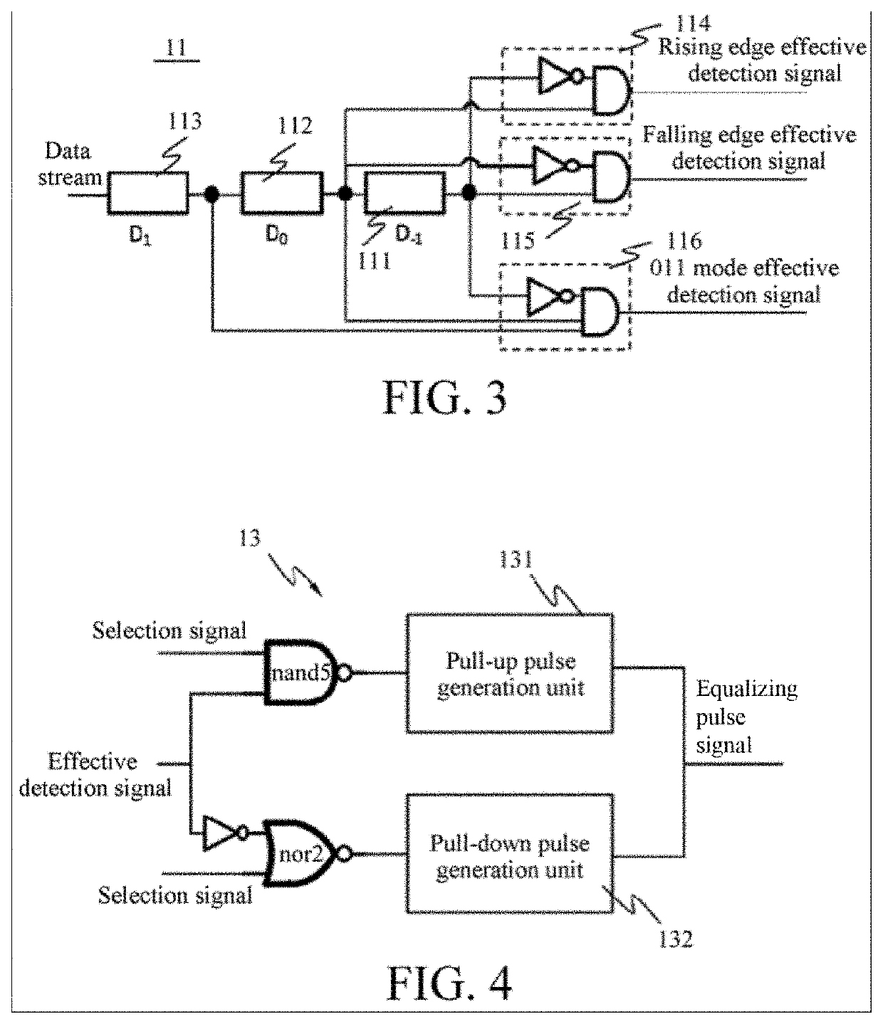
[0071]As shown in FIG. 2, this embodiment provides a pulse generation module 1, including a mode detector 11, a controller 12, and an equalizing pulse generator 13.
[0072]As shown in FIG. 2, the mode detector 11 receives a data stream, detects a jump mode of each piece of data in the data stream, and outputs a corresponding effective detection signal after detecting a preset mode.
[0073]Specifically, as shown in FIG. 2, the data stream includes a plurality of serially transmitted digital signals, and each piece of data is denoted in sequence as: . . . D1, D0, D−1 . . . , where D−1 represents a previous piece of data, D0 represents a current piece of data, and D1 represent a next piece of data.
[0074]Specifically, as shown in FIG. 3, the mode detector 11 includes three latch units, which are separately a first latch unit 111, a second latch unit 112, and a third latch unit 113. The third latch unit 113 is configured to latch a third bit of data D1 in three continuous bits of data, the s...
embodiment 2
[0106]This embodiment provides a pulse generation module for fourth-order pulse amplitude modulation (PAM 4), and differs from Embodiment 1 in that, four jump levels of a data stream in the pulse generation module are provided.
[0107]Specifically, as shown in FIG. 8 and FIG. 9, four jump levels are provided, which are sequentially a first level 00, a second level 01, a third level 10, and a fourth level 11 in ascending order. A mode detector 21 detects that a jump mode includes jumps between four levels. As shown in FIG. 10 and FIG. 11, the mode detector includes three groups of phase inverters 211, fifth latch units 213, and fourth latch units 212 that are sequentially connected in series, a second rising edge effective signal generation unit 214, a third rising edge effective signal generation unit 216, a second falling edge effective signal generation unit 215, and a third falling edge effective signal generation unit 217. The fourth latch unit 212 is configured to latch an invert...
embodiment 3
[0118]As shown in FIG. 13, this embodiment provides an optical communication transmitter system, including: a clock data recovery module 3, the pulse generation module 1, a temperature detection module 4, a laser driving module 5, and an addition module 6.
[0119]As shown in FIG. 13, the clock data recovery module 3 is configured to: process clock and data signals, and provide processed clock and data information.
[0120]Specifically, the clock data recovery (CDR) module 3 recovers an embedded clock from data, and rebuilds a received signal waveform by using an extracted clock signal to generate a recovered data signal. The clock signal extracted by the clock data recovery module 3 and a data signal recovered by the clock data recovery module 3 are full-rate signals or half-rate signals.
[0121]As shown in FIG. 13, the pulse generation module 1 is connected to an output end of the clock data recovery module 3, and generates a corresponding equalizing pulse signal according to an output si...
PUM
 Abstract
Description
Claims
Application Information
 - R&D
- Intellectual Property
- Life Sciences
- Materials
- Tech Scout
- Unparalleled Data Quality
- Higher Quality Content
- 60% Fewer Hallucinations
Browse by: Latest US Patents, China's latest patents, Technical Efficacy Thesaurus, Application Domain, Technology Topic, Popular Technical Reports.
© 2025 PatSnap. All rights reserved.Legal|Privacy policy|Modern Slavery Act Transparency Statement|Sitemap|About US| Contact US: help@patsnap.com


