Supercharge Your Innovation With Domain-Expert AI Agents!

Method for detecting an operational condition of a multi-conductor cable

a multi-conductor, data-transfer technology, applied in the direction of electric variable regulation, line-transmission details, instruments, etc., can solve the problem of aforementioned tdr devices being the perceived minimum system rise time of these prior-art devices, and being difficult to deploy outside the laboratory environmen

Active Publication Date: 2020-08-25
MOHR & ASSOC INC
View PDF6 Cites 0 Cited by
  • Summary
  • Abstract
  • Description
  • Claims
  • Application Information

AI Technical Summary

Benefits of technology

This approach provides accurate and interpretable results for detecting operational conditions, including fault locations, in a lightweight, cost-effective, and user-friendly manner, comparable to prior art devices but overcoming their limitations.

Problems solved by technology

While these aforementioned TDR devices, as utilized heretofore, have operated with varying degrees of success, problems persist with their usefulness in certain critical applications.
One of the limitations of the aforementioned TDR devices is the perceived minimum system rise time for these prior art devices.
Still further, these same prior art devices which have been utilized, heretofore, to determine and detect these reflected electrical signals have often been difficult to deploy outside a laboratory environment because of their size or complexity, or on the other hand, have repeatedly shown that they are less than accurate regarding detecting various electrical conditions in the transmission, multi-conductor or data transfer cable, which is being studied or tested.
Further, these same prior art TDR devices, and the electrical traces they produce are often very difficult to interpret except for the most skilled technicians.
Moreover, and while, in theory, the distance to an electrical problem that a multi-conductor or data transfer cable may have can be calculated or otherwise determined from a reflected electrical signal which is received from the multi-conductor or data transfer cable, this calculation has often-times proved more difficult to accurately calculate than what the available prior art information on this subject matter would tend to suggest.

Method used


Image

  • Method for detecting an operational condition of a multi-conductor cable
  • Method for detecting an operational condition of a multi-conductor cable
  • Method for detecting an operational condition of a multi-conductor cable

Examples


Embodiment Construction

[0022]This disclosure of the invention is submitted in furtherance of the constitutional purposes of the U.S. Patent Laws “to promote the progress of science and useful arts” (Article 1, Section 8).

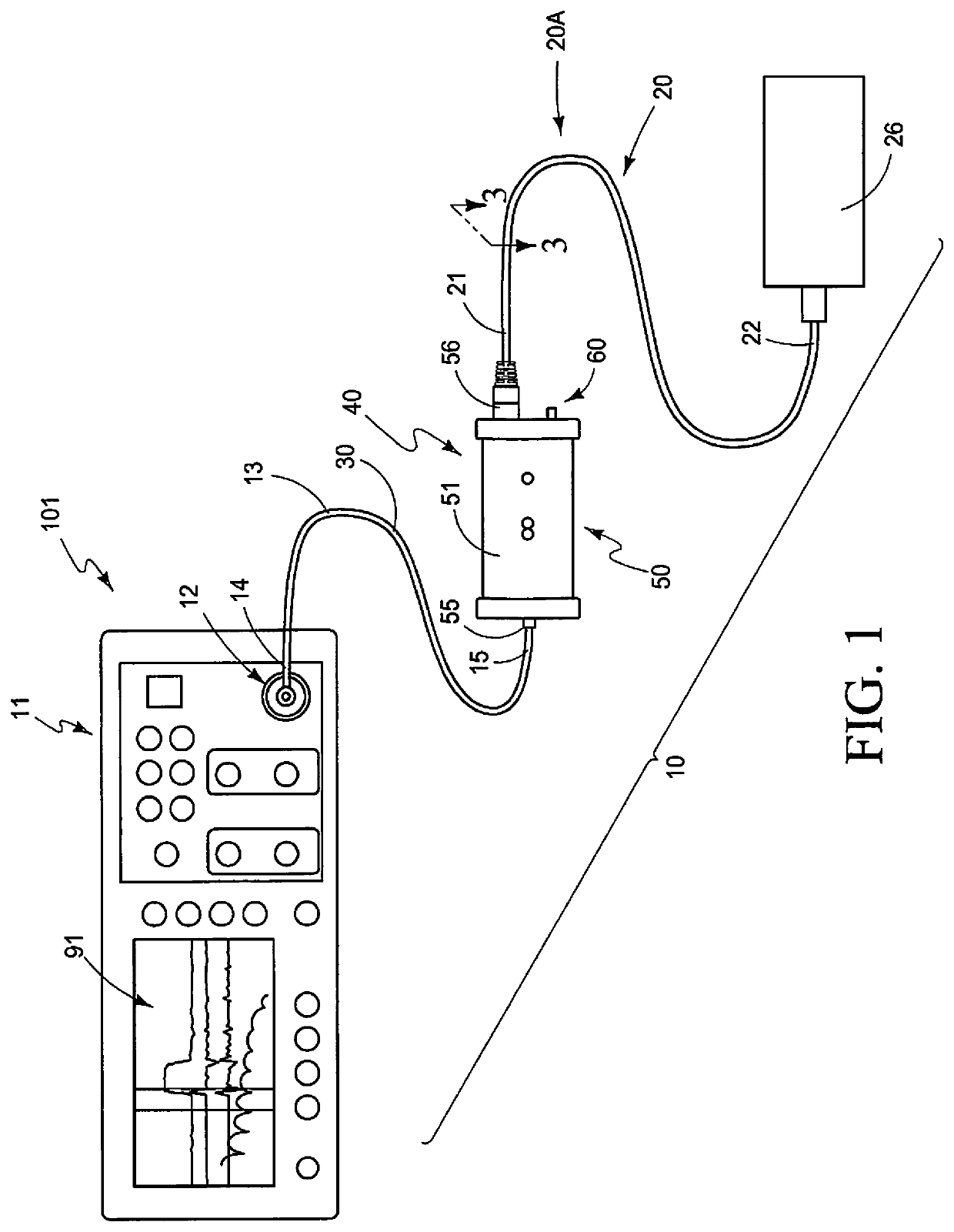
[0023]The method for detecting an operational condition of a multi-conductor or data transfer cable is generally indicated by the numeral 10, in FIG. 1, and following. As seen in the drawings, the present invention includes a step of providing a single channel, metallic, time domain reflectometer 11, and which is operable, when selectively energized, to provide a first, single ended, time domain reflectometer signal which will be utilized in further steps of the present methodology, as described, below. A suitable time domain reflectometer, as mentioned, above, can be commercially purchased under the trademark MOHR CT100B Cable Tester™. The time domain reflectometer 11 as illustrated in FIG. 1 includes a test port 12, and which will electrically couple with a test coupling cable which is ...


PUM


Abstract

A method for detecting an operational condition of a multi-conductor cable is described, and which includes generating a first, single ended, time domain reflectometer signal which is introduced into a multi-conductor cable; processing the first, single ended, time domain reflectometer signal so as to generate a first, differential time domain reflectometer signal; supplying the first, differential time domain reflectometer signal to the multi-conductor cable; converting a reflected, differential time domain reflectometer signal into a second, single ended, time domain reflectometer signal; numerically and / or graphically analyzing the second, single ended, time domain reflectometer signal; and identifying, by the numerical and / or graphical analysis, an operational condition of the multi-conductor cable undergoing the testing.

Description

TECHNICAL FIELD[0001]The present invention relates to a method for detecting an operational condition of a multi-conductor or data transfer cable, and more specifically, to a methodology which facilitates the detection of operational defects that may occur, from time-to-time in a multi-conductor or data transfer cable including, but not limited to, locating electrical faults of various types along the length of the multi-conductor or data transfer cable; verifying the electrical termination of the same multi-conductor or data transfer cable; measuring the differential impedance along the multi-conductor or data transfer cable; and inspecting various electrical connections that might be made to the same multi-conductor or data transfer cable.BACKGROUND OF THE INVENTION[0002]For decades, time domain reflectometry has been used to measure the electrical reflections that result from an electrical signal traveling through a transmission environment of some kind. This environment could in...

Claims


Application Information

Patent Timeline
Patent Type & Authority Patents(United States)
IPC IPC(8): G01R31/11H04B3/46G01R27/06G05F1/10
CPCG01R27/06G01R31/11G05F1/10H04B3/46
Inventor MOHR, CHARLES L.MOHR, BRANDT C.MAY, PRESTONCOTTAM, TONYVON REIS, ERIKMULKEY, CHRISTOPHERSAMS, RYANKENNEY, DANIELRAUSCH, WILLIAMDAWES, KEVIN
Owner MOHR & ASSOC INC
Features
  • R&D
  • Intellectual Property
  • Life Sciences
  • Materials
  • Tech Scout
  • Unparalleled Data Quality
  • Higher Quality Content
  • 60% Fewer Hallucinations
Learn More