
Corrugated stent

a corrugated stent and stent technology, applied in the field of corrugated stents, can solve the problems of limiting the useful exposure to a short range of x-rays, affecting the patient's recovery, and affecting the patient's recovery, and the patient is subject to the additional risk of multiple procedures

Active Publication Date: 2020-09-15
HERSKOVIC ARNOLD M
View PDF5 Cites 0 Cited by
  • Summary
  • Abstract
  • Description
  • Claims
  • Application Information

AI Technical Summary

Benefits of technology

[0021]Yet another object of the invention is to provide a reversible deformable receiver for medicaments, wherein the receiver resides within a patient. A feature of the receiver is that it is adapted to support medicaments such as radioisotopes, therapeutic materials, pharmaceuticals, drugs, diagnostic materials, biologically active compounds or materials, or any other medicament, wherein the medicament resides on the outer surface of the receiver, concentrated at a specific region of the carrier, or else dispersed homogeneously throughout the carrier. An advantage of the invention is that the medicament may be applied locally in a focalized manner to target tissues. Another advantage is that the medicament receivers may be modified to facilitate medicament diffusion or movement from the receivers to target tissue once the carrier expands to contact the surfaces of the surgically produced void.
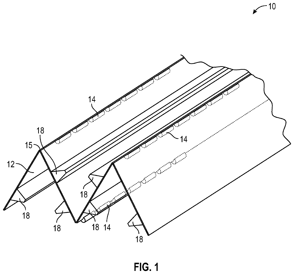
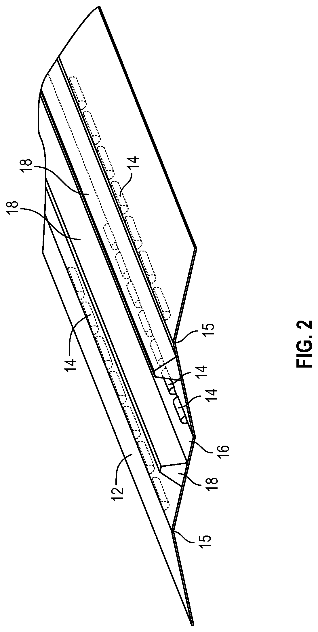
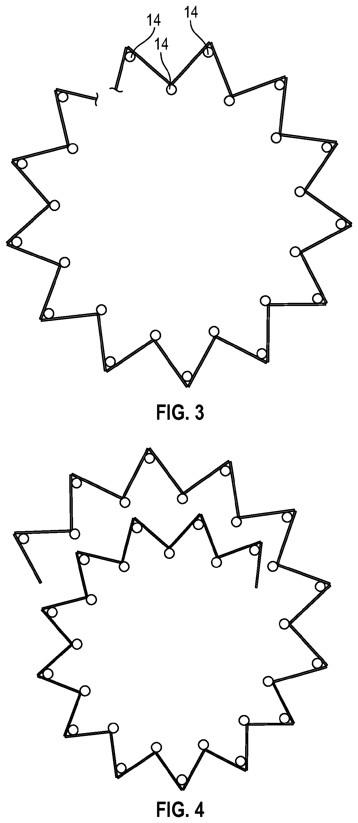
[0022]Briefly, the invention provides a material for brachytherapy comprising: a substrate having a longitudinal axis and a latitudinal axis, wherein the substrate comprises a plurality of generally flat panels connected to each other at alternating peaks and valleys which are parallel to the longitudinal axis, the alternating peaks and valleys defining latitudinally extending pleats; and a plurality of medicament moieties positioned on the peaks and valleys of the substrate.
[0023]The invention also provides a frustoconical shaped carrier of radioactive particles for use in in situ tumor treatment
[0024]Also provided is a carrier of radioactive particles for brachytherapy, the carrier comprising a base defining a center region and a periphery; a plurality of leaves, each of said leaves defining a first proximal end hinge-ably attached to the periphery of the base, a second free distal end, and side edges extending from the first end to the second end; and radioactive seeds positioned along the side edges.

Problems solved by technology

Individual seeds are shielded by the encapsulation process which usually limits the useful exposure to a short range of x- or gamma-rays.
Host factors such as oxygenation, intrinsic radio sensitivity, proliferation rate, and repair capacity are more difficult to control.
Thus, the patient is subjected to the additional risk of multiple procedures, often requiring anesthesia.
Such protracted use of catheters often leads to kinking, dislodgement, obstruction, irritation, and the risk of life-threatening infections.
Thus, brachytherapy treatment using a centralized radioactive material housing or containment can result in significant patient toxicity if the radioactive source is too close to normal or target tissues.
However, there are many reasons for the source to be skewed to one side as even an active tumor could displace the source.
Leaving a permanent radiation source in a patient, where it or its carrier may migrate over time or the tumor may change in shape or size, has the potential undesirable effect that healthy tissue will be exposed to the excessive radiation, while the target cancerous tissue is not.
The ability to remove the radioactive sources in this situation or prior to surgery, while clinically useful, is currently lacking from the state of the art, as is the ability to easily localize the brachytherapy treatment or stent in vivo in the doctor's office without requiring formal imaging.
However, state of the art methods for delivering radiation at these margin areas after tumor excision have drawbacks.
But the suture positions shift in time and the mesh may be absorbed by the body.
This often leads to the sutures sometimes collapsing on themselves, and otherwise not maintaining the optimal seed positioning relative to the neoplasm or vulnerable tissue.
Under-dosing occurs, which can lead to recurrence.
Conversely, over dosing occurs, leading to injury to healthy tissue.

Method used


Image

  • Corrugated stent
  • Corrugated stent
  • Corrugated stent

Examples


example

[0098]A preferred embodiment is the use of shaped soft tissue equivalent carriers in which a permanent radioactive seed is centrally spaced (or otherwise optimally spaced viz the effected tissue). Palladium and Iodide seeds are attractive commercially available radio isotopes. The seeds placed in such a carrier are usually homogeneously (i.e. evenly) spaced when subsequently placed within a target volume. Bunching of sources in a specific area and other volumes in which there is a paucity of sources is avoided.

[0099]A suitable material would have similar consistency of the normal tissue it is replacing (such as breast), and be hypo allergenic. This material would not leak and would have an appropriate geometry. Also, the RDC defines a shape similar to the dose pattern of the radioisotope seed utilized. This prevents over exposure and uneven dosages to the tissue requiring treatment.

[0100]Spacers comprised of inert material can be used to separate and or link seeds together. The spac...


PUM


Abstract

A material for brachytherapy is provided comprising a substrate having a longitudinal axis and a latitudinal, wherein the substrate comprises alternating peaks and valleys which are parallel to the longitudinal axis, the alternating peaks and valleys defining latitudinally extending pleats; and a plurality of medicament moieties positioned on the peaks and valleys of the substrate.

Description

FIELD OF INVENTION[0001]The present invention relates to a device and method for delivering medicaments and more particularly, the present invention relates to a device and a method for treating cancers and tumors with radiation.BACKGROUND[0002]Some cancers and neoplasms are easier to treat with radiation than others. Hard-to-reach and and / or remove neoplasms, such as those in the esophagus, intestines and other lumens, are often treated via Brachytherapy. Brachytheraphy uses radioactive isotopes (commonly employed as seeds) to minimize radiation to adjacent, healthy tissue.[0003]The radiation (dose distribution) depends on geometry especially the inverse square law, filtration by encapsulation material, and also adsorption in tissue and air. Individual seeds are shielded by the encapsulation process which usually limits the useful exposure to a short range of x- or gamma-rays. The initial dose rate would vary inversely with half-life. As an example, the typical initial dose rate fo...

Claims


Application Information

Patent Timeline
Patent Type & Authority Patents(United States)
IPC IPC(8): A61N5/00A61M36/00A61M36/04A61M36/12A61N5/10
CPCA61N5/1007A61N2005/1025A61N2005/1011A61N5/1001
Inventor HERSKOVIC, ARNOLD M.
Owner HERSKOVIC ARNOLD M
Learn More