Structural suspension of radial turret bearings

a technology of radial turret bearings and structural suspension, which is applied in the direction of sliding contact bearings, vessel construction, transportation and packaging, etc., can solve the problems of requiring space for hydraulic and spring packages, the system of hydraulic springs of radial bearings is comprehensive and complicated,

Active Publication Date: 2020-09-29
APL NORWAY AS
View PDF10 Cites 0 Cited by
  • Summary
  • Abstract
  • Description
  • Claims
  • Application Information

AI Technical Summary

Benefits of technology

[0011]Furthermore the inner side of the rail is a frustum with the shortest radius at the top and an aperture of 2, and the outer mainly planar contacting surface of the wheel has an angle θ relative to the rotational axis of the wheel, and is overlaid with a convex curvature across the contacting surface. The axis of the wheel is tilting an angle A relative to the unloaded position of the axis, when the shaft is under maximum load, and an angle E between and the tangent of the curvature across the contacting surface is less than zero at the top for conditions without load and larger than A at the bottom for conditions with maximum load. The flexibility and length of the shafts, the clearance between the wheels and rail, and the positions of the upper and lower shaft supports are chosen such that the sector distributing the radial load on the rail increases as the radial load increases.

Problems solved by technology

Hydraulic spring systems in radial bearing systems are comprehensive and complicated, especially the control system.
A further challenge to spring systems is the combination of transverse loads and movements while subject to simultaneous axial displacements; A radial bearing unit will thus be subjected both to horizontal forces from horizontal turret displacements within the rail system and lateral loads caused by turret vertical displacements: A main contribution to lateral loads is vertical friction effects from the combined effect of horizontal bearing loads and vertical turret displacement.
Furthermore, the hydraulic and spring packages require space, much because of the need to handle the lateral loads.

Method used


Image

  • Structural suspension of radial turret bearings
  • Structural suspension of radial turret bearings
  • Structural suspension of radial turret bearings

Examples


Embodiment Construction

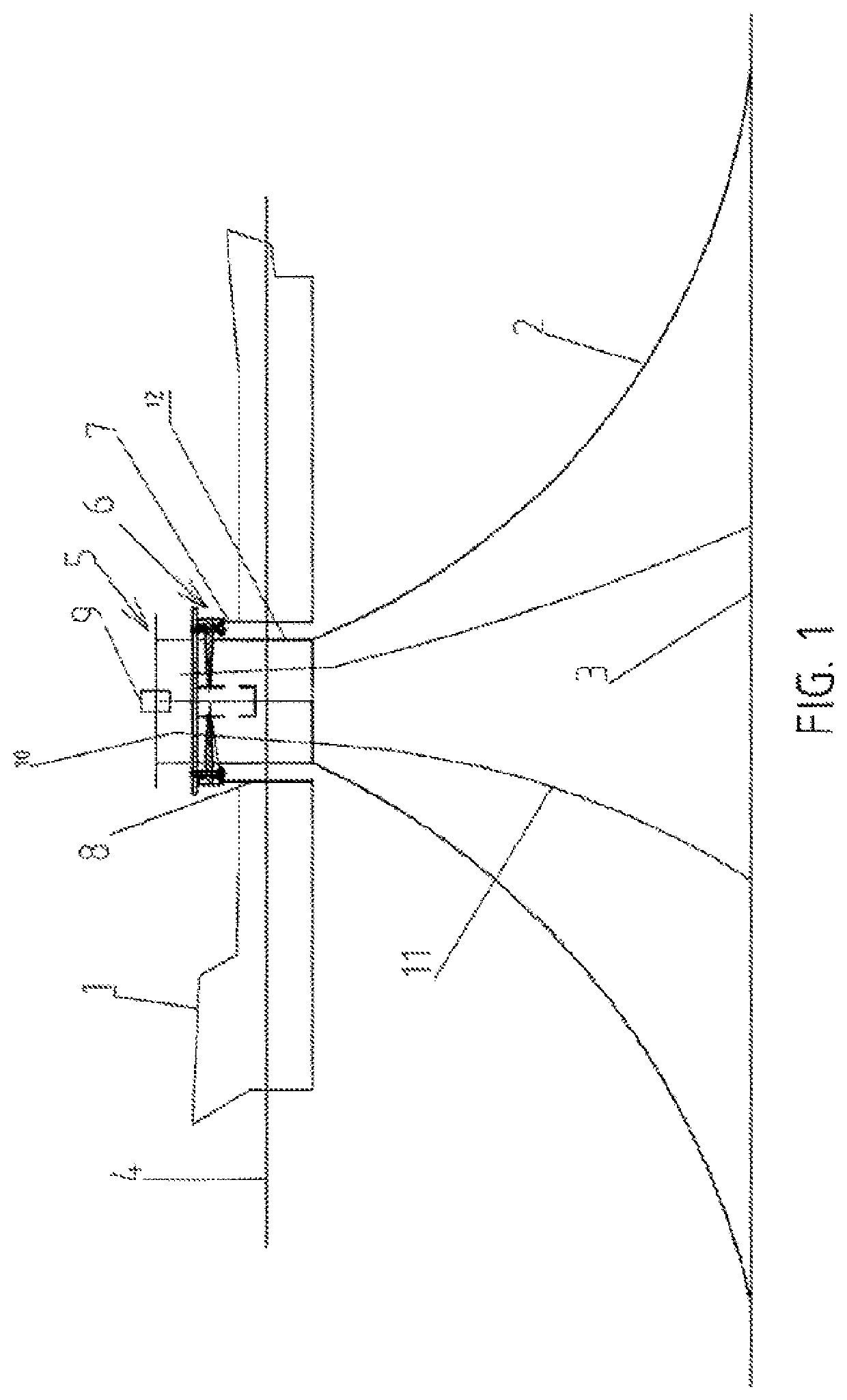
[0027]Directions referred to in this text are related to a turret 5 with a vertical central axis in operation at sea 4. It is also conceivable that the turret could be mounted at an angle, but to make writing easier this is omitted in the text.

[0028]FIG. 1 is showing a turret moored vessel 1. A turret barrel 12 is rotating inside a turret well 8 and is geostationary relative to the sea floor 3 and the mooring lines 2 keep the vessel in position and the risers 11 connects the flowlines (not shown) at the sea floor with the vessel through the riser termination piping 10 in the turret through the rotary pipe connection (swivel) 9. The turret bearing 6 features an endless low-torque rotation of the vessel relative to the turret.

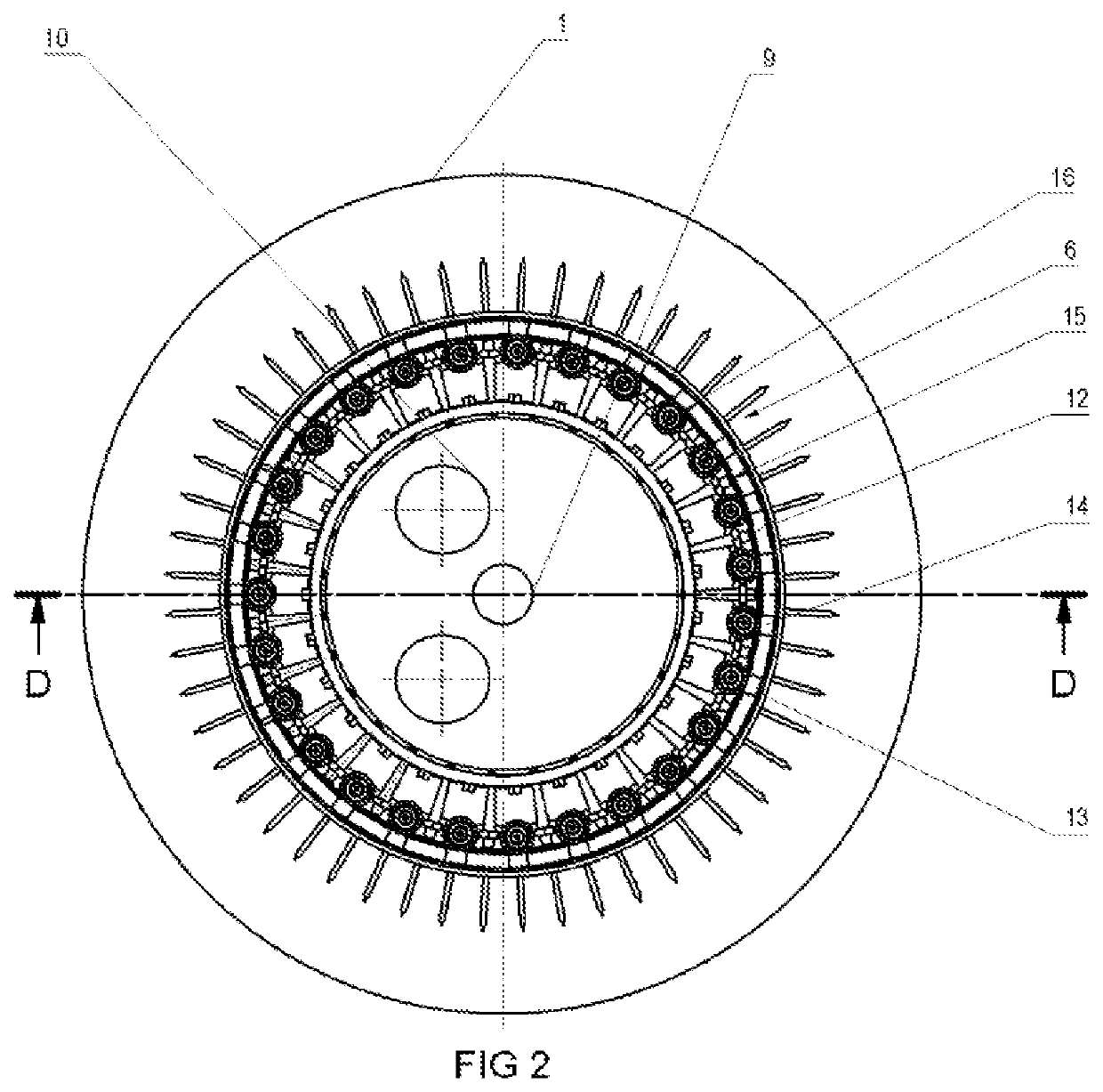
[0029]FIG. 2 is showing the plan or top view of the turret with turret bearing 6. Radial wheels 16 are horizontally mounted on the inside of the rail 14 and transfers the horizontal component of the turret loads, from mooring and the riser system in particular, t...


PUM


Abstract

A structural suspension of radial turret bearing wheels in a turret bearing comprises a rail support structure mounted on a turret bearing support structure, a circular rail mounted to the rail support structure, and a plurality of radial wheels running on the mainly vertical inner side of the rail. The suspension includes a vertical flexible shaft, for each radial wheel, supported by an upper and lower support with a part of the shaft protruding with the radial wheel mounted close to the outer end. The inner side of the rail is a frustum with the shortest radius at the top and an aperture of 2, and the outer mainly planar contacting surface of the wheel has an angle θ relative to the rotational axis of the wheel, and is overlaid with a convex curvature across the contacting surface.

Description

CROSS-REFERENCE TO RELATED APPLICATIONS[0001]This patent application is the U.S. National Stage of International Patent Application No. PCT / NO2017 / 000036, filed Dec. 21, 2017, which claims the benefit of Norwegian Patent Application No. 20162053, filed Dec. 23, 2016, which are each incorporated by reference.TECHNICAL FIELD[0002]This invention relates to offshore installations, in particular to a structural suspension of radial turret bearings for handling the large radial loads in a turret bearing system usually found at the surface termination of a riser on a turret mooring related to extraction of hydrocarbons. A method for changing the position of a shaft relative to the rail is also provided.BACKGROUND[0003]Turret mooring systems have been in use for some decades and as the search for hydrocarbons has increased, the depth from which hydrocarbons can be extracted has increased. The risers coming from greater depths are associated with greater loads and the turret bearings now hav...

Claims


Application Information

Patent Timeline
Patent Type & Authority Patents(United States)
IPC IPC(8): B63B21/50F16C19/34F16C19/54F16C23/04
CPCF16C23/045F16C19/34B63B21/507F16C19/545F16C2300/14F16C23/02B63B21/50
Inventor ASKESTAD, SIGMUND
Owner APL NORWAY AS
Why Eureka
Try Eureka