Supercharge Your Innovation With Domain-Expert AI Agents!

Apparatus for controlling sample position in a liquid chromatography system

a liquid chromatography system and apparatus technology, applied in the direction of selective adsorption, ion exchange process apparatus, instruments, etc., can solve the problems of significant concerns such as leakage from the compartment and condensation generated in the compartment, space constraints within the hplc or uplc, and limit the location of the motor and mechanism used to control the position of the sample needl

Active Publication Date: 2020-09-29
WATERS TECH CORP
View PDF21 Cites 0 Cited by
  • Summary
  • Abstract
  • Description
  • Claims
  • Application Information

AI Technical Summary

Benefits of technology

This patent describes apparatus for controlling the position of a sample in a liquid chromatography system. The apparatus includes a rotary drive mechanism, a stepper motor, and a drive belt or coupling element. The methods of the patent involve rotating the sample vial containing multiple sample fluids in a forward and reverse direction at different speeds to achieve mixing of the fluids. The technical effect of this patent is to provide a more efficient and effective way to mix samples in a liquid chromatography system.

Problems solved by technology

Space constraints within a HPLC or UPLC system can limit the location of motors and mechanisms used to control the position of the sample needle.
In addition, thermal control of the sample compartment makes leakage from the compartment and condensation generated within the compartment significant concerns.
Moreover, in some test configurations, a buildup of volatile gas can occur in the sample compartment such that motor operation within the compartment is undesirable.

Method used


Image

  • Apparatus for controlling sample position in a liquid chromatography system
  • Apparatus for controlling sample position in a liquid chromatography system
  • Apparatus for controlling sample position in a liquid chromatography system

Examples


Embodiment Construction

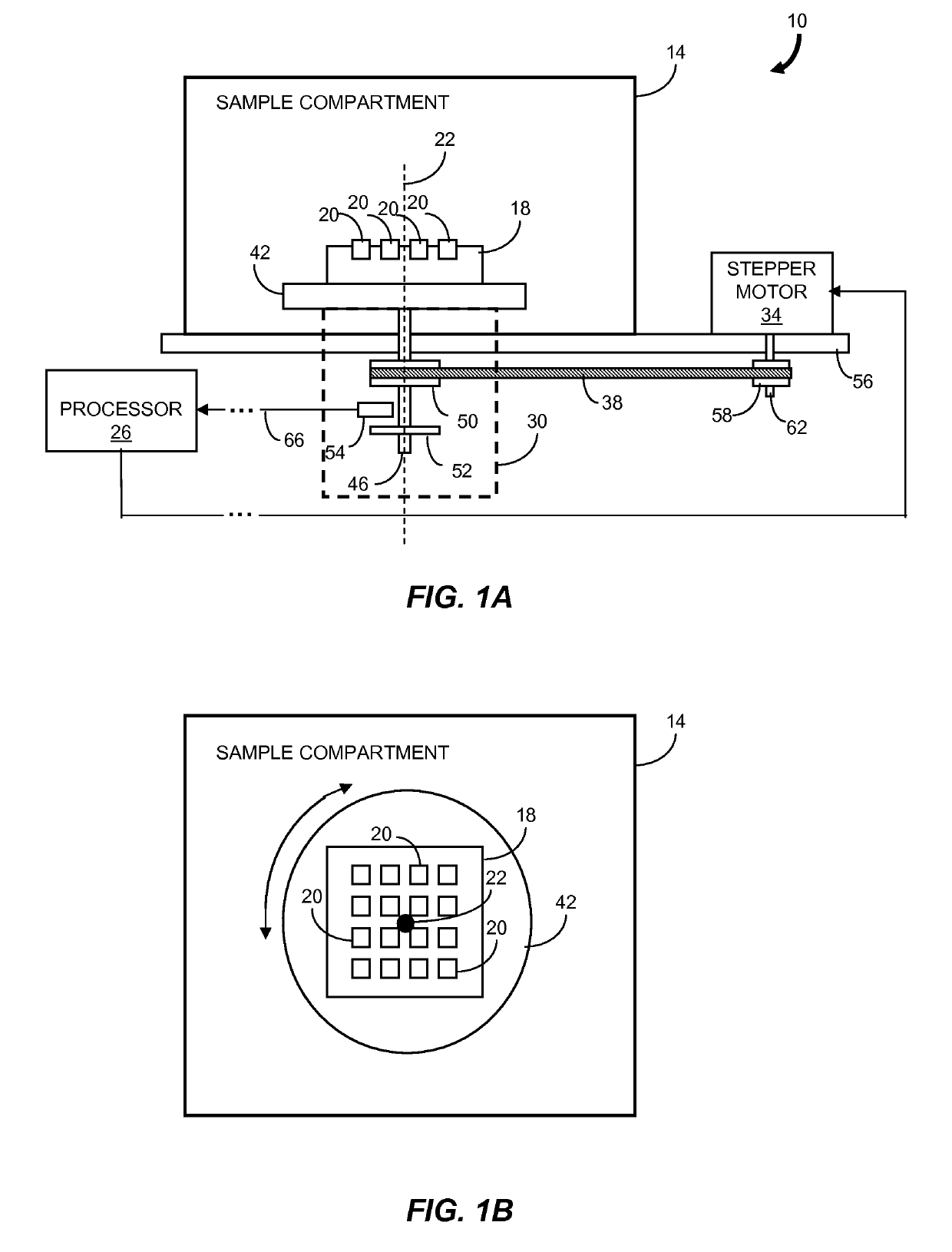
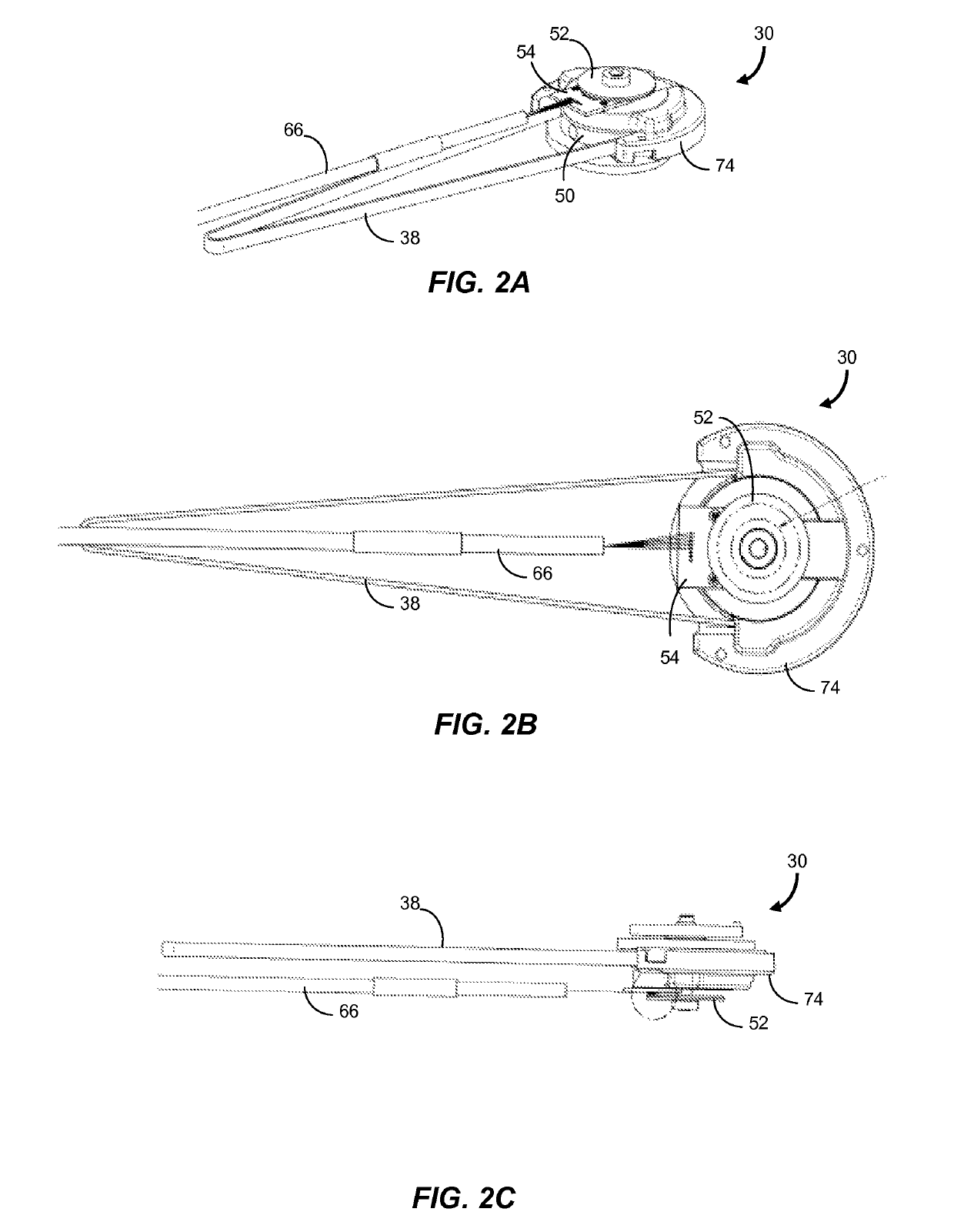
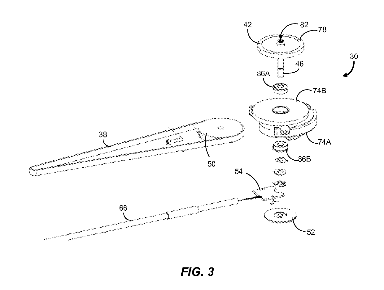
[0016]In brief overview, the invention relates to an apparatus for controlling a position of a sample in a liquid chromatography system. The apparatus includes a rotary drive mechanism, a stepper motor and a rotational coupling system such as a drive belt and pulley system. The rotational coupling system transfers the rotational motion of a motor shaft to a shaft of the rotary drive mechanism. The shaft extends through a wall of a sample compartment of the liquid chromatography system. Advantageously, the stepper motor is remote to the sample compartment to improve safety for instances when volatile gas accumulates within the sample compartment. As used herein, a stepper motor means any motor that rotates a motor shaft in fixed increments. The rotary drive mechanism can be configured in a small form factor and can provide highly stable rotation of an attached sample tray to accommodate the requirements of compact liquid chromatography systems. In addition, leakage from inside the sa...


PUM

PropertyMeasurementUnit
frequencyaaaaaaaaaa
frequencyaaaaaaaaaa
rotation rateaaaaaaaaaa

Abstract

Described is an apparatus for controlling a position of a sample in a liquid chromatography system. The apparatus includes a rotary drive mechanism, a stepper motor and a rotational coupling system such as a drive belt and pulley system. The rotational coupling system transfers the rotational motion of a motor shaft to a shaft of the rotary drive mechanism. Advantageously, the stepper motor is remote to the sample compartment for improved safety in the event that volatile gas accumulates within the sample compartment. The rotary drive mechanism can be configured in a small form factor and can provide highly stable rotation of an attached sample tray to accommodate the requirements of compact liquid chromatography systems. In addition, leakage from inside the sample compartment to the ambient environment is substantially reduced or eliminated, resulting in better thermal control of the sample compartment.

Description

RELATED APPLICATION[0001]This application claims the benefit of the earlier filing date of U.S. Provisional Patent Application Ser. No. 61 / 293,858, filed Jan. 11, 2010 and titled “Apparatus for Controlling Sample Position in a Liquid Chromatography System,” the entirety of which is incorporated herein by reference.FIELD OF THE INVENTION[0002]The invention relates generally to liquid chromatography systems. More particularly, the invention relates to an apparatus for controlling a sample position in a liquid chromatography system.BACKGROUND[0003]High performance liquid chromatography (HPLC) and ultra performance liquid chromatography (UPLC) systems typically include a sample compartment that is adapted for receiving a number of sample vials or wells each containing a sample for analysis. Sample vials are arranged in one or more sample trays that can be loaded into and removed from the sample compartment by a user. Some systems use an automated process in which the sample needle is mo...

Claims


Application Information

Patent Timeline
Patent Type & Authority Patents(United States)
IPC IPC(8): G01N35/02G01N35/04B01D15/08
CPCG01N35/025G01N2035/0491G01N2035/0484G01N2035/0475G01N2035/0441B01D15/08
Inventor BURNETT, JOSHUA A.USOWICZ, JAMES E.LEMELIN, MARC
Owner WATERS TECH CORP
Features
  • R&D
  • Intellectual Property
  • Life Sciences
  • Materials
  • Tech Scout
  • Unparalleled Data Quality
  • Higher Quality Content
  • 60% Fewer Hallucinations
Learn More