
Particle separation and/or purification of a fluid

a technology of particle separation and fluid, applied in the direction of filtration separation, membranes, separation processes, etc., can solve the problems of reducing the space occupied by the platform in comparison, affecting the efficiency of the platform, so as to optimize the operation of the platform and reduce the space requirements. , the effect of small footprin

Active Publication Date: 2020-10-06
SARTORIUS STEDIM BIOTECH GMBH
View PDF49 Cites 0 Cited by
  • Summary
  • Abstract
  • Description
  • Claims
  • Application Information

AI Technical Summary

Benefits of technology

The patent text is about a filter system that can produce different products by simply changing the configuration of the filters. The system can increase the amount of product produced per volume of fluid by further processing the fluid after it has been processed by one set of modules in the filter system. This further processing can include purification and / or a different type of filtering. The changing of the configuration can be done easily and flexibly, and it can reduce the cost of producing the product. In summary, the technical effect of this patent text is to provide a flexible and cost-effective filter system that can produce different products with different configurations.

Problems solved by technology

The cost of the process typically includes separate equipment and space costs for control and processing hardware associated with each process step.
Accordingly, there may be considerable overlap and redundancy between different process steps.
This may reduce the space occupied by the platform in comparison to conventional approaches.
In particular, the protecting parts form a contact protection means with regard to the filter medium, with result that the filter element and the filter medium cannot be touched by hand.
Further, the filter module may be designed to be disposable, such that the filter module is thrown away or destroyed after use.
Thus, access to the filter element or filter medium may be unnecessary.
Less expensive filter media can be provided as a result.

Method used


Image

  • Particle separation and/or purification of a fluid
  • Particle separation and/or purification of a fluid
  • Particle separation and/or purification of a fluid

Examples


Embodiment Construction

[0131]In the following text, a detailed description of examples will be given with reference to the drawings. It should be understood that various modifications to the examples may be made. In particular, one of more elements of one example may be combined and used in other examples to form new examples.

[0132]As used herein, the singular forms “a”, “an,” and “the” include plural unless the context clearly dictates otherwise.

[0133]In the context of the present application, when a filter module includes a filter, this may be understood to mean that a filter element of the filter module includes a filter medium with the filter.

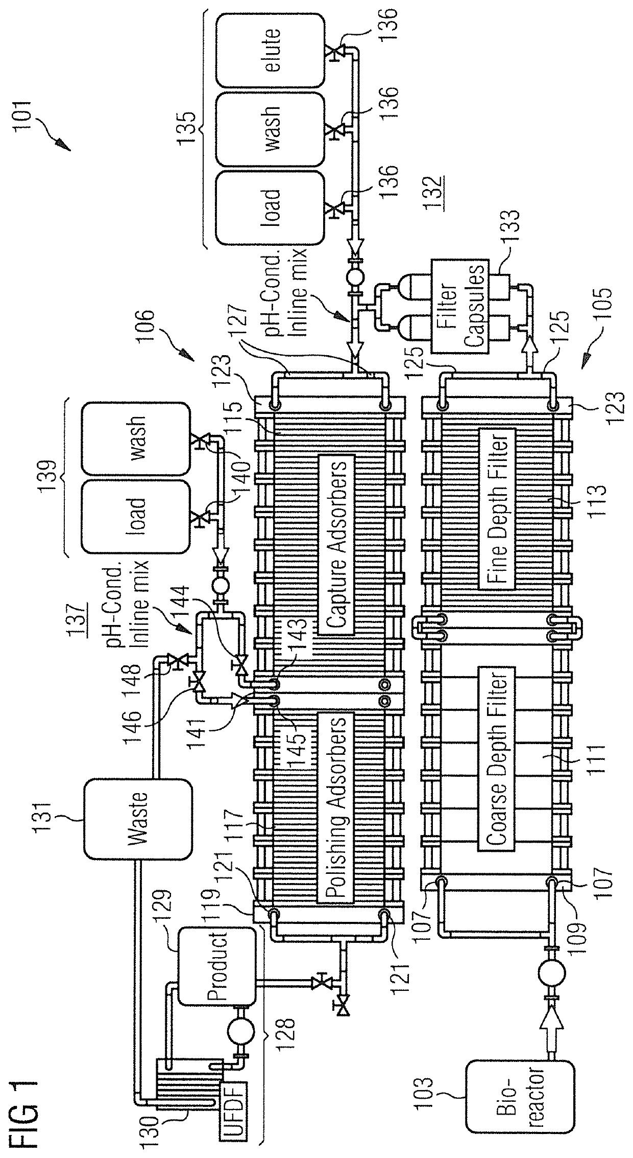
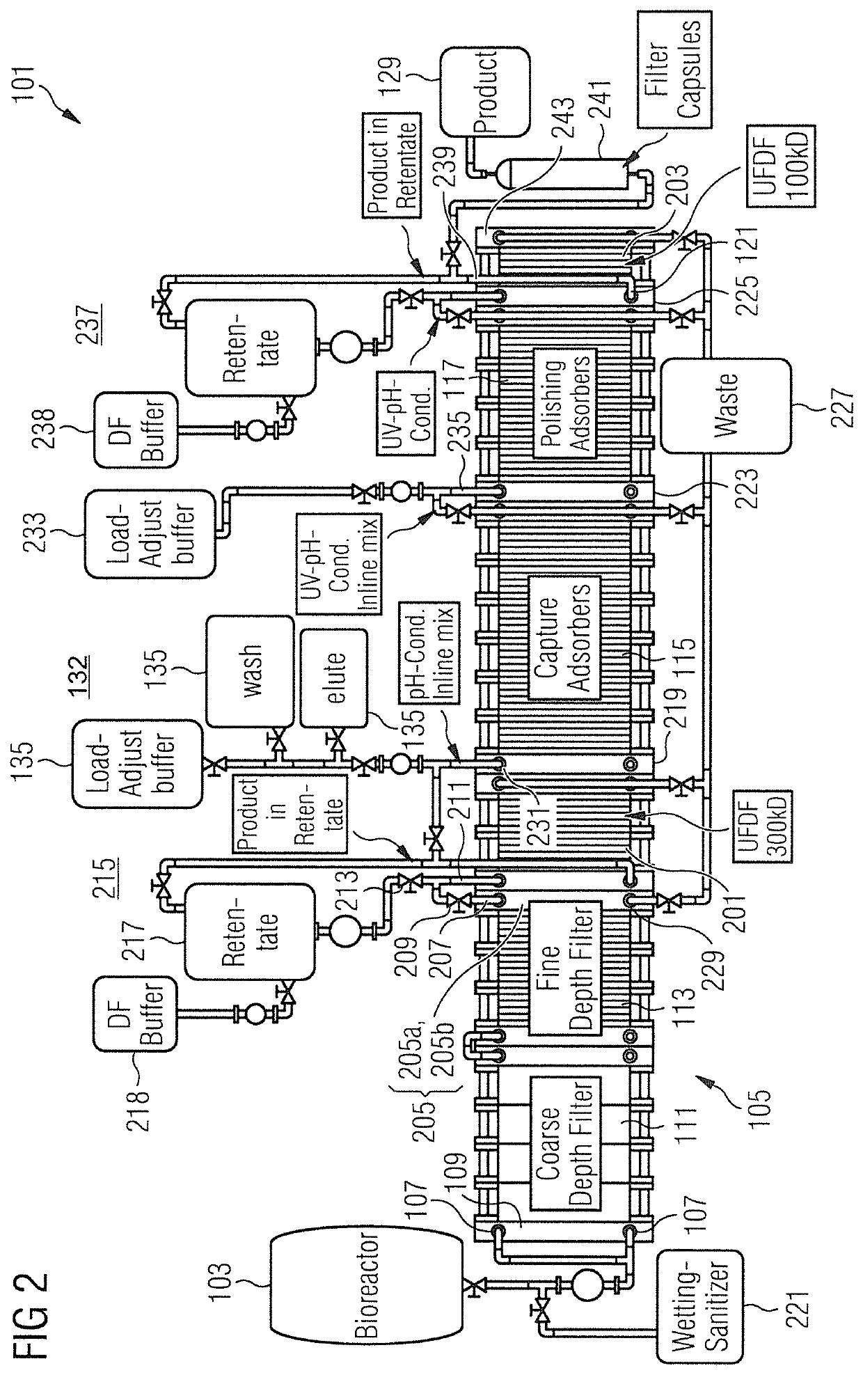
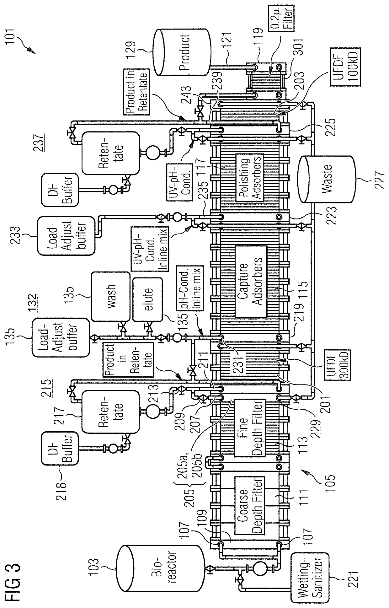
[0134]FIG. 1 shows a platform 101 for processing a fluid. The platform 101 may be used to perform particle separation and / or purification of the fluid, e.g., in order to limit the contents of the fluid (as far as possible) to constituents of interest. In particular, the platform 101 may receive a feed as fluid and produce a chemical, pharmaceutical, and / or biolog...


PUM


Abstract

A platform has a filter system with a first set of filter modules and a second set of filter modules that is different from the first set of filter modules. Each set of filter modules includes an inflow channel and an outflow channel. A fluid inlet is connected to the first set of filter modules, a fluid outlet is connected to the second set of filter modules, and a separation interface separates the first and second sets of filter modules. The separation interface has a first interface channel to connect to the module outflow channel of the first set of filter modules, and a second interface channel to connect to the module inflow channel of the second set of filter modules. The filter system receives fluid through the fluid inlet and, after the fluid has passed through each set of filter modules, discharges the fluid through the fluid outlet.

Description

BACKGROUNDField of the Invention[0001]The present application relates to separation of constituents of interest from a fluid (e.g., particle separation) and / or purification of the fluid. In particular, the present application relates to a platform for performing particle separation of the fluid and / or purification of the fluid and a method for configuring the platform.Related Art[0002]Unless otherwise indicated herein, the approaches described in this section are not prior art to the claims in this application and are not admitted to be prior art by inclusion in this section.[0003]Purification and / or particle separation may be performed in order to produce a chemical, pharmaceutical, and / or biological product from a fluid. The fluid (i.e., liquid or gas) may include biomolecules. The product may be a biotechnological product. Production of the product may include depth filtration, body feed filtration, chromatography (e.g. membrane chromatography), tangential flow filtration (TFF), ...

Claims


Application Information

Patent Timeline
Patent Type & Authority Patents(United States)
IPC IPC(8): B01D61/14B01D61/32B01D53/04B01D61/58B01D61/24B01D61/18
CPCB01D53/0407B01D61/32B01D53/0454B01D61/58B01D61/142B01D61/18B01D61/246B01D2259/804B01D2315/10B01D2325/12B01D2201/32B01D2257/91B01D2319/06B01D2317/06B01D2315/08B01D2315/06B01D2311/2626B01D2311/2623B01D61/08B01D2311/2697B01D63/0822B01D61/149
Inventor ERDENBERGER, THOMAS
Owner SARTORIUS STEDIM BIOTECH GMBH
Learn More