Supercharge Your Innovation With Domain-Expert AI Agents!

Method for limiting interlaminar fatigue in composite laminate and a component incorporating the same

a composite laminate and interlaminar fatigue technology, applied in the field of composite laminates, can solve the problems of matrix cracks and/or structural risk, and achieve the effect of reducing the risk of delamination

Active Publication Date: 2020-10-06
BELL HELICOPTER TEXTRON INC
View PDF17 Cites 0 Cited by
  • Summary
  • Abstract
  • Description
  • Claims
  • Application Information

AI Technical Summary

Benefits of technology

The use of compliant layers reduces matrix crack initiation and delamination propagation, maintaining structural stiffness and load-carrying capability while prolonging the service life of composite components without significant cost increases or redesign efforts.

Problems solved by technology

The structure may have a risk of delamination and / or producing matrix cracks, especially when subjected to high cycle dynamic loading.

Method used


Image

  • Method for limiting interlaminar fatigue in composite laminate and a component incorporating the same
  • Method for limiting interlaminar fatigue in composite laminate and a component incorporating the same
  • Method for limiting interlaminar fatigue in composite laminate and a component incorporating the same

Examples


Embodiment Construction

[0016]Illustrative embodiments of the system and method of the present disclosure are described below. It will of course be appreciated that in the development of any such actual embodiment, numerous implementation-specific decisions must be made to achieve the developer's specific goals, such as compliance with system-related and business-related constraints, which will vary from one implementation to another. Moreover, it will be appreciated that such a development effort might be complex and time-consuming but would nevertheless be a routine undertaking for those of ordinary skill in the art having the benefit of this disclosure.

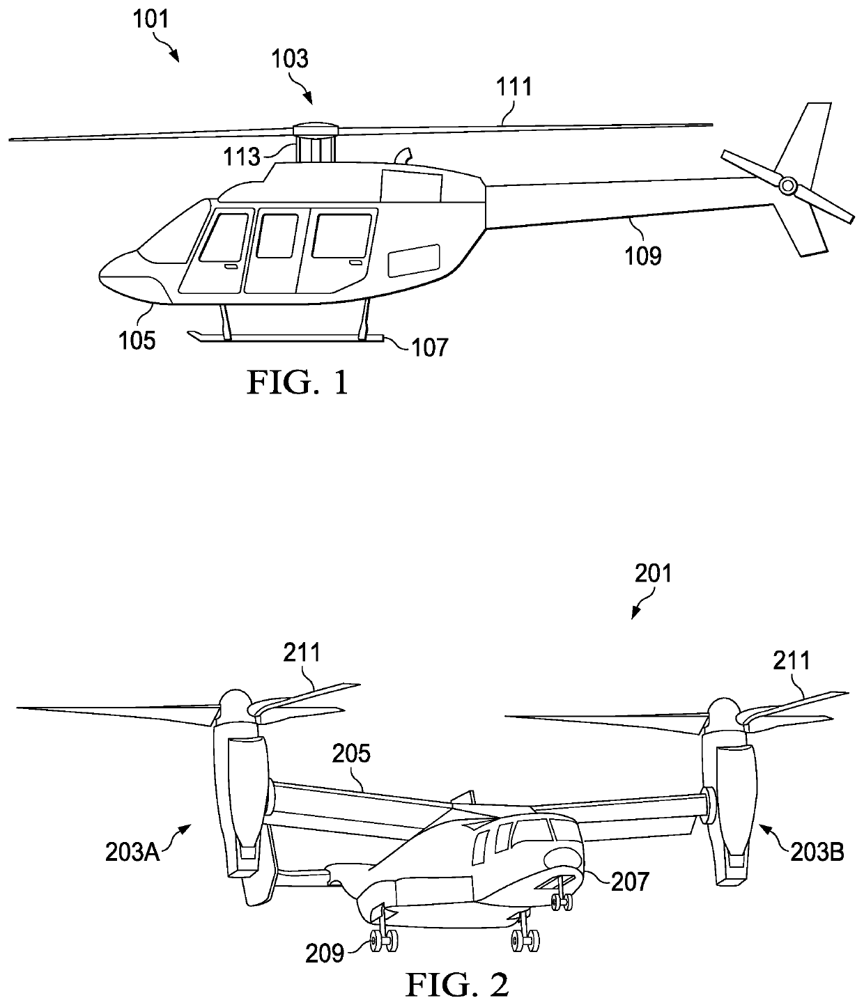
[0017]In the specification, reference may be made to the spatial relationships between various components and to the spatial orientation of various aspects of components as the devices are depicted in the attached drawings. However, as will be recognized by those skilled in the art after a complete reading of the present disclosure, the devices, members, ...


PUM

PropertyMeasurementUnit
tensile strengthaaaaaaaaaa

Abstract

In some embodiments, a rotor system for a rotorcraft includes a yoke, a blade, and a grip that is configured to couple the blade to the yoke. The grip has a plurality of baseline layers and a compliant layer. The baseline layers each have a plurality of fibers disposed in a first polymeric matrix. The compliant layer has a plurality of fibers disposed in a second polymeric matrix. The compliant layer is stronger than the baseline layer and the first polymeric matrix has a different chemical composition than the second polymeric matrix.

Description

BACKGROUND[0001]Technical Field[0002]This present disclosure relates generally to composite laminates.[0003]Description of Related Art[0004]Typically, composite laminate is manufactured from the same fibrous material and the same polymeric-matrix material, throughout. The structure may have a risk of delamination and / or producing matrix cracks, especially when subjected to high cycle dynamic loading. Hence, there is a need for an improved composite laminateDESCRIPTION OF THE DRAWINGS[0005]The novel features believed characteristic of the apparatus and method of the present disclosure are set forth in the appended claims. However, the apparatus and method itself, as well as a preferred mode of use, and further objectives and advantages thereof, will best be understood by reference to the following detailed description when read in conjunction with the accompanying drawings, wherein:[0006]FIG. 1 is a side view of a rotorcraft, according to an example embodiment;[0007]FIG. 2 is a persp...

Claims


Application Information

Patent Timeline
Patent Type & Authority Patents(United States)
IPC IPC(8): B32B7/02B32B37/14B32B27/08B32B27/38B32B5/14B29C70/30B29C70/06B29L31/30
CPCB32B27/08B29C70/06B29C70/30B32B37/144B32B5/142B32B27/38B32B2305/72B32B2262/0269B32B2262/101B32B2605/18B29L2031/3088B32B2262/106B32B2307/552
Inventor KRASNOWSKI, BOGDAN ROMANBRACK, ROBERT ARNOLDLI, XIAOMINGWARDLAW, ROBERT
Owner BELL HELICOPTER TEXTRON INC
Features
  • R&D
  • Intellectual Property
  • Life Sciences
  • Materials
  • Tech Scout
  • Unparalleled Data Quality
  • Higher Quality Content
  • 60% Fewer Hallucinations
Learn More