Card insertion structure

a card and insertion structure technology, applied in the field of card insertion structure, can solve the problem of not providing sufficient lock structur

Active Publication Date: 2020-10-06
PEGATRON
View PDF9 Cites 0 Cited by
  • Summary
  • Abstract
  • Description
  • Claims
  • Application Information

AI Technical Summary

Benefits of technology

[0006]The disclosure provides a card insertion structure that provides a lock structure sufficient for the electronic card to be secured to the portable electronic device without affecting the wireless transmission function of the portable electronic device.
[0017]Based on the above, the card insertion structure is configured in the manner that the pressing member and the plastic spring strip are disposed on the base of the housing of the portable electronic device and the portion of the pressing member is exposed out of the housing, such that the plastic spring strip leans against the pressing member and the base. In this manner, the user may apply a force to the portion of the pressing member exposed out of the housing to deform the plastic spring strip, so that the electronic card can be inserted into the card insertion structure smoothly. Then, after the electronic card is move and passes by the pressing member and the user removes the force, the pressing member is released and the resilience of the plastic spring strip can drive the pressing member to be restored. In the meantime, the portion of the pressing member exposed out of the housing is used as a lock structure for fixing the electronic card to the housing, thereby keeping the electronic card stable in the housing without being detached from the card insertion structure due to the movement of the portable electronic device, so that the portable electronic device can read the related information in the electronic card smoothly without being affected by the foregoing conditions.

Problems solved by technology

However, the related modules of existing portable electronic device for reading the electronic card do not provide sufficient lock structure to allow the electronic card to be securely inserted in the portable electronic device.
However, due to the trend of light weight, slim and short, basically, the antenna module of the portable electronic device must be adjacent to the reading module of the electronic card.
Therefore, in the design stage, technicians of the field still have to try to exclude any possible factors by which the antenna module might be affected by the reading module.

Method used


Image

  • Card insertion structure
  • Card insertion structure
  • Card insertion structure

Examples


Embodiment Construction

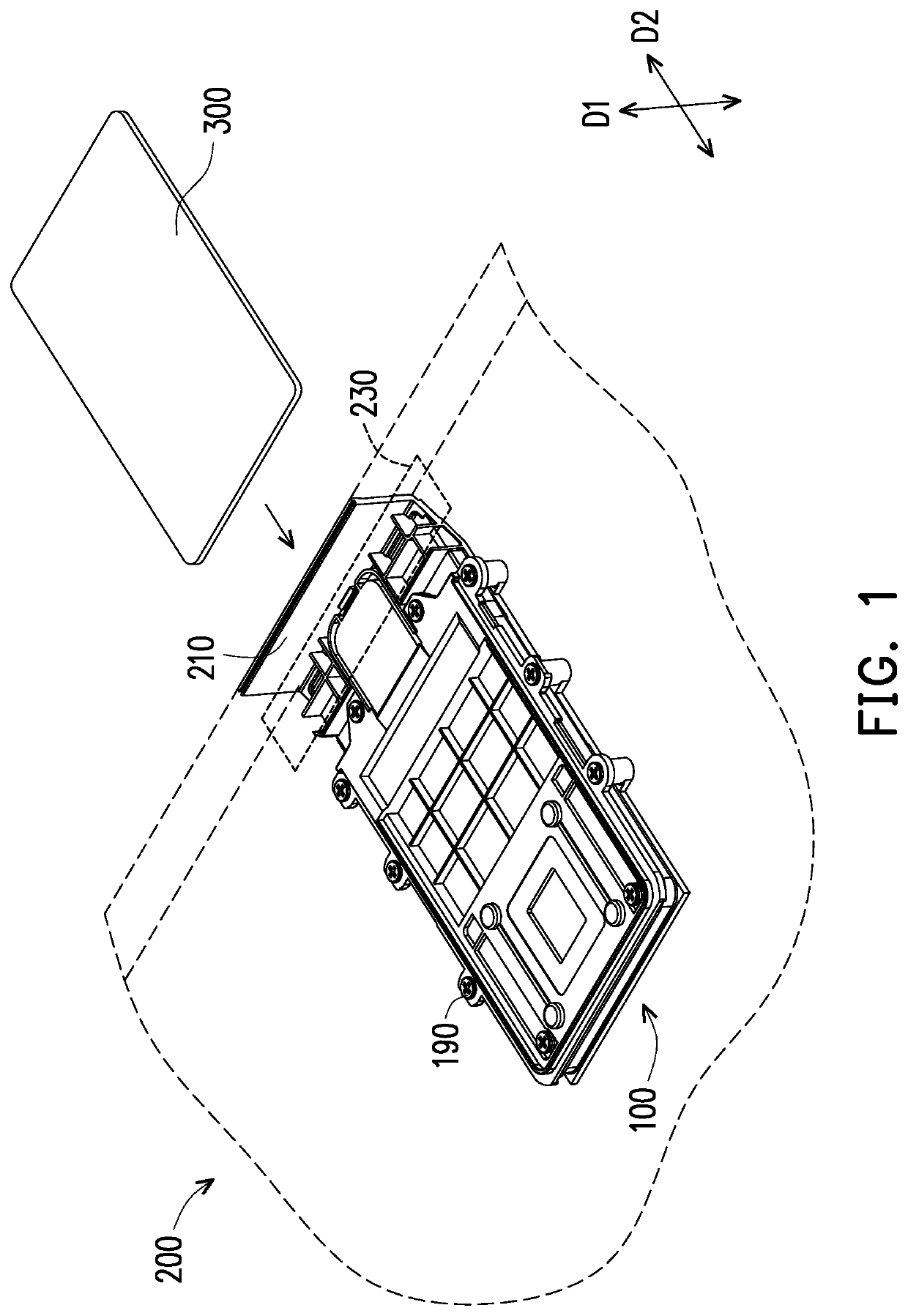
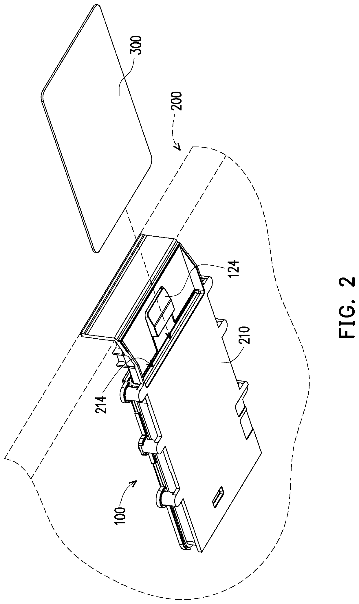
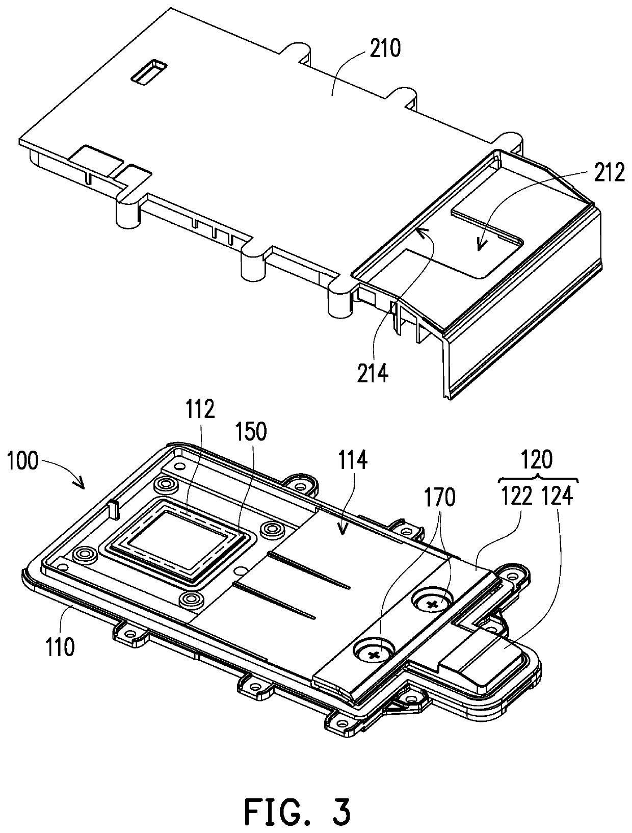
[0024]FIG. 1 is a partial schematic view of a card insertion structure applied to a portable electronic device according to an embodiment of the disclosure. FIG. 2 is a schematic view of FIG. 1 from another perspective. FIG. 3 is a schematic view illustrating initial assembly of the card insertion structure and corresponding housing. Referring to FIG. 1 to FIG. 3, in this embodiment, a card insertion structure 100 is disposed in a housing 210 of a portable electronic device 200 and is used to accommodate and position an electronic card 300 (e.g., an IC card, a smart card, etc.). Meanwhile, after the electronic card 300 is inserted into the housing 210 and carried on a stage 114, the control system (not shown) of the portable electronic device 200 can read the information in the inserted electronic card 300 through a reading module 112.

[0025]FIG. 4 and FIG. 5 are schematic views illustrating the respective assembly of the card insertion structure and the corresponding housing, which ...


PUM


Abstract

A card insertion structure suited for a portable electronic device is provided. The portable electronic device includes a housing. The card insertion structure includes a base disposed in the housing, a pressing member movably disposed on the base, and a plastic spring strip disposed on the base. A portion of the pressing member is exposed out of the housing. The plastic spring strip leans against the pressing member and the base. A force supplied via an insertion of an electronic card drives the pressing member to deform the plastic spring strip, and after the electronic card passing by the pressing member and being inserted into the card insertion structure between the base and the housing, the pressing member is released and is restored by resilience of the plastic spring strip, and the electronic card is fixed with the housing by the pressing member.

Description

CROSS-REFERENCE TO RELATED APPLICATION[0001]This application claims the priority benefit of Taiwan application serial no. 107202090, filed on Feb. 9, 2018. The entirety of the above-mentioned patent application is hereby incorporated by reference herein and made a part of this specification.BACKGROUNDTechnology Field[0002]The disclosure is related to a card insertion structure, and particularly a portable electronic device using a card insertion structure thereof.Description of Related Art[0003]With the evolution of the information technology, the electronic cards have become part of people's daily lives, so everyone carries a variety of electronic cards with them for use in every aspect of life. Accordingly, portable electronic devices have also been updated, and they are able to read related information from the above-mentioned electronic card, bringing more convenience in life everywhere.[0004]However, the related modules of existing portable electronic device for reading the ele...

Claims


Application Information

Patent Timeline
Patent Type & Authority Patents(United States)
IPC IPC(8): G06K7/00H01Q1/22H01Q1/24H04B1/3816H04B1/3818
CPCH01Q1/2216G06K7/0056H01Q1/243H04B1/3818
Inventor GUO, GUO-LONGHUANG, HO-CHINGTSAI, WEN-CHENG
Owner PEGATRON
Why Eureka
Try Eureka