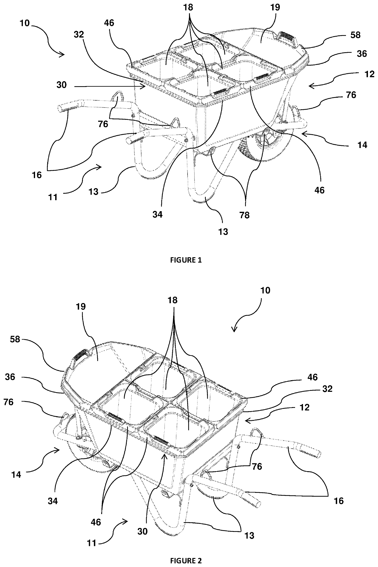
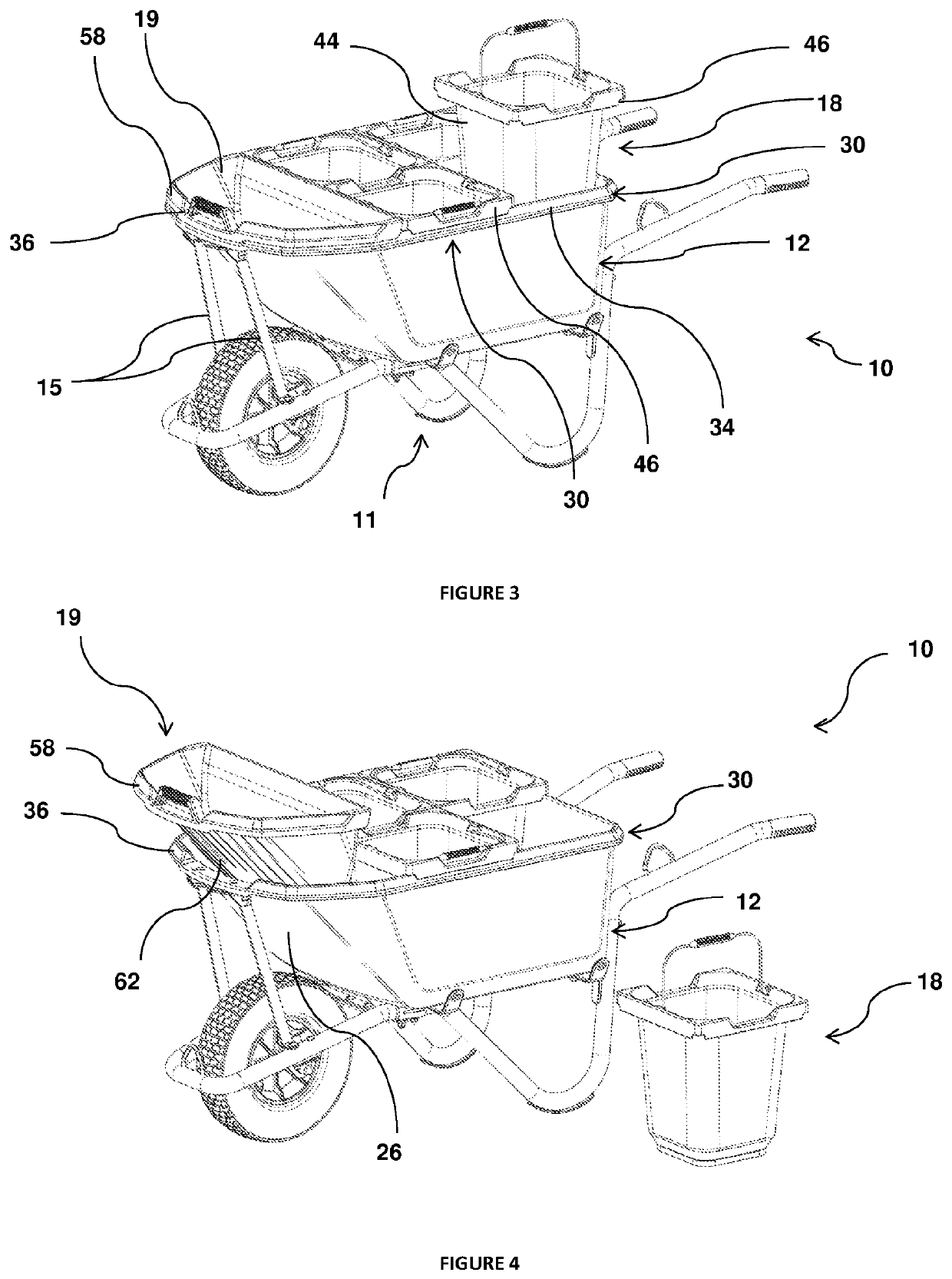
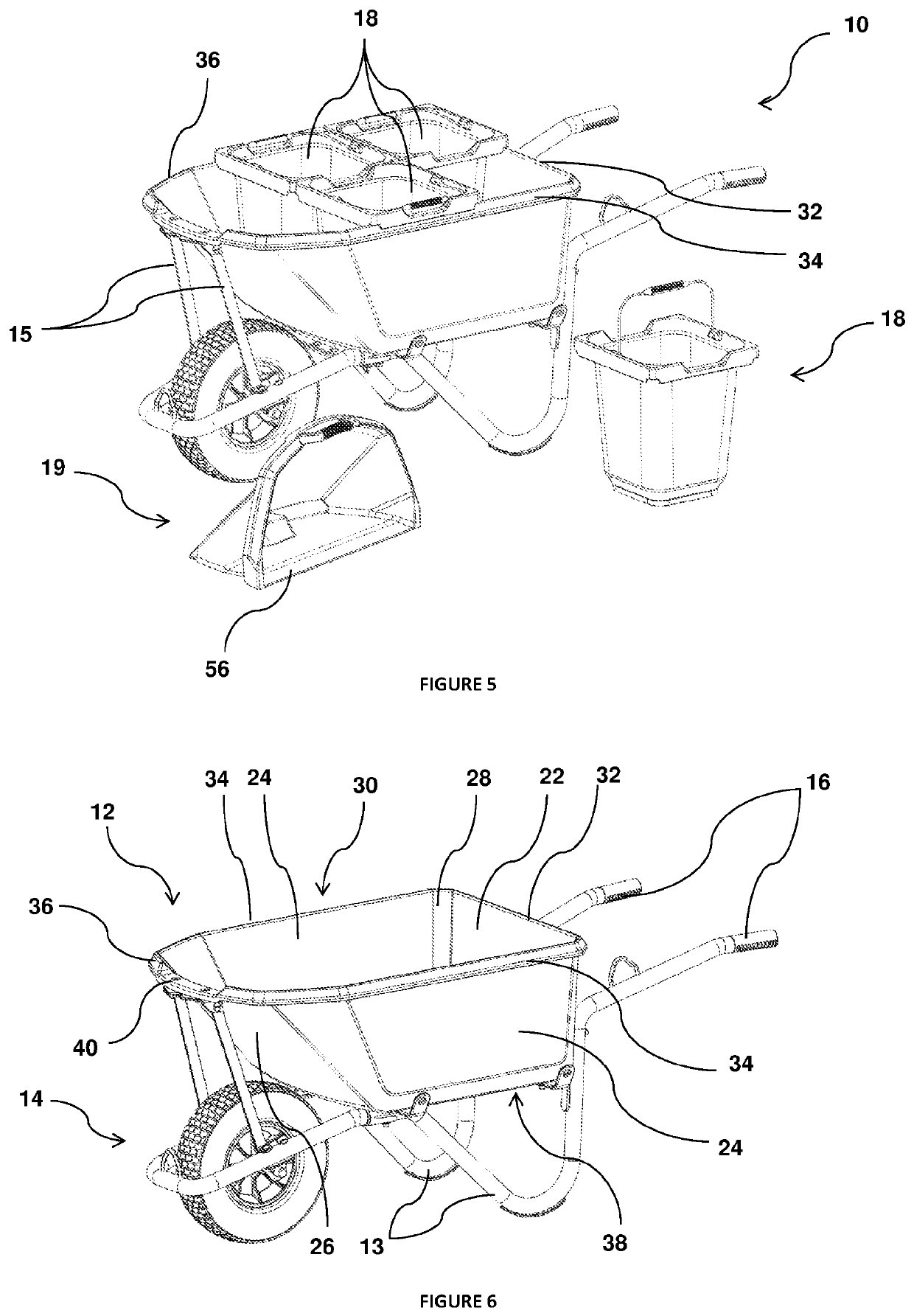
Wheelbarrow

a technology of wheelbarrows and sleds, which is applied in the field of wheelbarrows, can solve the problems of damage to vehicles, unsafe or impossible to traverse, and difficulty in lifting a loaded wheelbarrow to the necessary elevation in order to tip, so as to facilitate connection to a lifting device, facilitate transportation, and facilitate the effect of movemen

Active Publication Date: 2020-10-13
MSP INNOVATIONS PTY LTD
View PDF46 Cites 2 Cited by
  • Summary
  • Abstract
  • Description
  • Claims
  • Application Information

AI Technical Summary

Benefits of technology

[0014]According to the present invention there is provided, a wheelbarrow including: a receptacle comprising a tub for carrying a load of material; a wheel assembly facilitating movement of the wheelbarrow; a handle for controlling operation of the wheelbarrow; and a plurality of removable compartments located within the receptacle, each for containing a portion of the load of material, the receptacle and each removable compartment being configured to interact with each other so as to, in use, hinder movement of each compartment relative to the receptacle.
[0015]A wheelbarrow according to the present invention therefore allows for a load of material to be transported from a filling location to an emptying location in a safer, more robust and more convenient manner than a conventional wheelbarrow or a conventional wheelbarrow haphazardly stacked with cylindrical buckets or other unsecured containers.
[0016]In use, the plurality of removable compartments may be filled in situ within the wheelbarrow receptacle or, alternatively, removed from the receptacle and conveniently brought closer to the filling site. In instances where the filling site maybe inaccessible for a wheelbarrow for example, a deep trench, the compartments can be individually carried into the trench and once filled to the desired level, the compartments may be returned to the receptacle ready for transport. Advantageously, the compartments and receptacle are configured to hinder movement of each compartment so as to secure each compartment in a desired position, or a desired range of positions, throughout transport. For this reason, the present invention represents a significant improvement in safety and convenience as compared to existing wheelbarrows and / or wheelbarrow practices. Moreover, the present invention allows obstacles encountered during load transport to be more easily negotiated with the convenient removal of one or more compartments (and a portion of the load contained therein). In this regard, the removal of a compartment advantageously reduces the weight of the wheelbarrow thereby improving manoeuvrability as well as enabling easier and safer lifting of the wheelbarrow, if necessary. In instances where the use of a crude ramp cannot be avoided, the present invention thus enables the traversing of the ramp with a higher degree of safety and convenience. In other instances, the present invention may eliminate the need for traversing a ramp altogether when the emptying location is sufficiently nearby that compartments can be removed and portions of the load carried the remainder of the way to the emptying location.

Problems solved by technology

However, in practice, an operator may encounter a variety of obstacles or hazards which prevents or limits access of the wheelbarrow to the desired position.
In this regard, obstacles such as stairs, uneven terrain or muddied ground may be difficult, unsafe or impossible to traverse with a filled wheelbarrow tub and particularly if the operator is alone.
Moreover, in instances where the filling or emptying location is elevated, for example a skip bin or a utility vehicle tray, it may be impossible for a loaded wheelbarrow to be lifted to the necessary elevation in order for tipping / emptying to occur.
This practice, however, is highly dangerous in that a loaded wheelbarrow, often weighing in excess of 150 kg, must be pushed up a narrow ramp at the risk of falling backwards or sideways, in either case potentially falling onto the operator causing injury, damaging the vehicle and spilling the load.
Another example of undesirable, yet common, wheelbarrow practice involves a pair of operators lifting loaded wheelbarrows up stairs or above their heads to empty the wheelbarrow contents into a skip bin.
This practice places the operators at high risk of injury or strain from the lift and an even greater risk of injury in the event that the wheelbarrow or the material within is accidently dropped onto one of the operators.
Furthermore, the practice of lifting a loaded wheelbarrow up stairs or pushing a loaded wheelbarrow up a makeshift ramp markedly increases the chance of spillage occurring thereby resulting in a waste of materials and a time consuming mess to be cleaned up.
Moreover, these practices usually require additional operators to suspend their activities to help the primary operator push or lift the wheelbarrow, thus reducing overall efficiency at the work site.
Utilising 20 litre buckets allows for manual handling of smaller portions of material mass however the cylindrical buckets are haphazardly arranged within a wheelbarrow tub and buckets are unsecured against toppling over within the tub or even falling out of the tub if they are stacked sufficiently high.
Moreover, a large portion of tub volume between the buckets is unutilised resulting in a highly inefficient use of the wheelbarrow tub volume.

Method used


Image

  • Wheelbarrow
  • Wheelbarrow
  • Wheelbarrow

Examples


third embodiment

[0113]FIG. 16 illustrates a wheelbarrow 200 according to the present invention having an oval-shaped 80 litre tub 212 and a 3-compartment configuration consisting of a pair of 15 litre buckets 218 and a single 15 litre scoop 219. Tub 212 has a lower profile or shallower configuration and may therefore be particularly suited to use with a domestic concrete mixer which are often located close to the ground. The rear of tub 212 is left unoccupied by a compartment so as to allow, for example, gloves, spades or other items to be carried in front of the operator. In alternative forms, wheelbarrow 200 may be fitted with a pair of scoops 219 at either end of the tub 212.

[0114]FIG. 17 illustrates a wheelbarrow 300 according to a fourth embodiment of the present invention including a 110 litre tub 312 similar in profile to tub 12 of the first embodiment but for a cut-out 380 in the lower rear section such that the rear portion of the tub 312 is shallower than the front portion. Cut-out 380 th...

fifth embodiment

[0117]FIG. 18 illustrates a wheelbarrow 400 according to the present invention having a 7-bucket extended tub 412. Seated upon the rim 430 of tub 412 are six buckets 418 and one scoop 419. At the rear of wheelbarrow 400 is a one-piece handle 416. As compared to the foregoing embodiments, wheelbarrow 400 includes additional buckets therefore allowing for a larger amount of material to be transported. Wheelbarrow 400 includes a wheel assembly comprising a pair of wheels 414 located on opposite sides of the tub 412.

sixth embodiment

[0118]FIG. 19 illustrates a wheelbarrow 500 according to the present invention. As distinct from the foregoing embodiments and illustrations, the tub 512 of wheelbarrow 500 includes a linear front wall 526 such that the profile and the rim 530 of wheelbarrow 500 are generally rectangular. As such, wheelbarrow 500 does not include a scoop compartment. Instead, wheelbarrow 500 includes six buckets 518. Wheelbarrow 500 is envisioned, in particular, for sorting applications such as fruit or vegetable picking where the tub 512 will seldom be used to carry materials directly and therefore a spout-shaped front wall is generally not necessary. Instead, wheelbarrow 500 includes six buckets 518 for carrying / sorting a variety of materials. Wheelbarrow 500 includes a wheel assembly comprising a pair of wheels 514 located on opposite sides of the tub 512.

[0119]It will be appreciated that, in contrast to the wheelbarrows illustrated in the foregoing Figures, wheelbarrow 500 includes a generally v...


PUM


Abstract

A wheelbarrow (10) including a receptacle (12) comprising a tub for carrying a load of material; a wheel assembly facilitating movement of the wheelbarrow; a handle for controlling operation of the wheelbarrow; and a plurality of removable compartments (18, 19) located within the receptacle (12), each for containing a portion of the load of material. The receptacle (12) and each removable compartment (18, 19) are configured to interact with each other so as to, in use, hinder movement of each comportment (18, 19) relative to the receptacle (12).

Description

TECHNICAL FIELD[0001]The present invention relates generally to a wheelbarrow. In particular, the invention has been developed for use as a manually operated wheelbarrow and will hereinafter generally be described in this context. However, it is to be appreciated that the invention is not necessarily limited to this application and may also relate, for example, to powered wheelbarrows or other types of load carrying trolleys and carts in the field of wheelbarrows.BACKGROUND OF INVENTION[0002]The following discussion of the background to the invention is intended to facilitate an understanding of the invention. However, it should be appreciated that the discussion is not an acknowledgement or admission that any of the material referred to was published, known or part of the common general knowledge as at the priority date of the application.[0003]Conventional wheelbarrows provide a convenient means by which a relatively large volume of material, typically 60-200 litres, can be manual...

Claims


Application Information

Patent Timeline
Patent Type & Authority Patents(United States)
IPC IPC(8): B62B1/00B62B1/20B62B1/26B62B1/22B62B5/06B62B3/14
CPCB62B1/26B62B1/202B62B1/22B62B5/06B62B3/1464B62B2202/12B62B1/204
Inventor PAINO, MICHAELDAVIES, PAUL EDWARD
Owner MSP INNOVATIONS PTY LTD
Why Eureka
Try Eureka