
Pelvic anchor for penile prosthetic implants

a technology for prosthetic implants and pelvis, applied in the field of medical devices implanted, can solve the problems of prone to withdrawal/disloyalty, difficult to achieve, and difficult to achieve, and achieve the effect of avoiding withdrawal/disloyalty, and avoiding the removal of the prosthesis

Active Publication Date: 2020-10-20
MHN BIOTECH LLC
View PDF4 Cites 0 Cited by
  • Summary
  • Abstract
  • Description
  • Claims
  • Application Information

AI Technical Summary

Benefits of technology

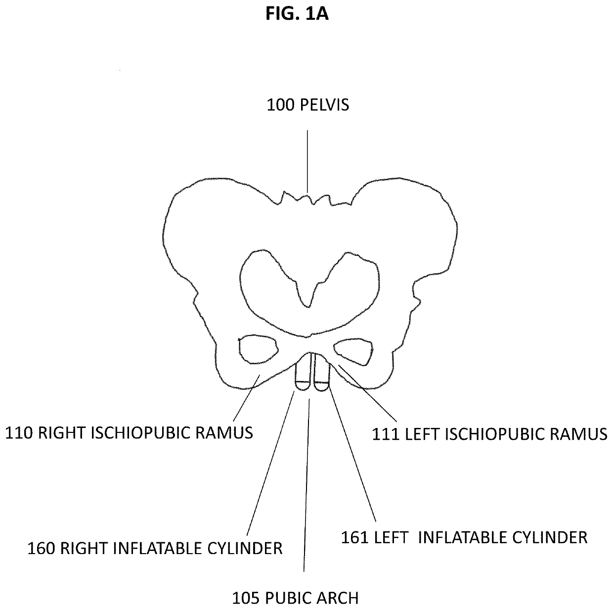
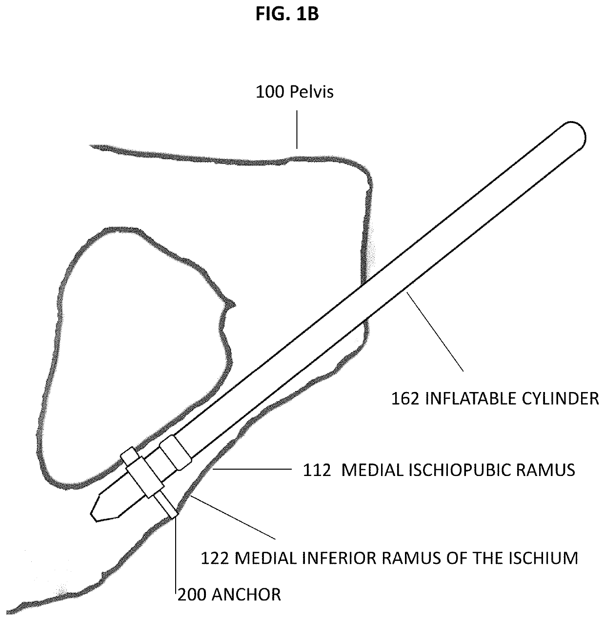
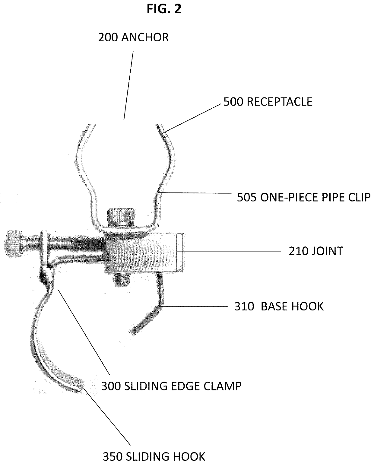
[0015]In an embodiment, the receptacle is in the form of a one-piece pipe clip which secures the endcap to the joint in a manor such that the prosthesis' cylinder lies close to and parallel with the medial ischiopubic ramus, with its proximal end lying along the medial inferior ramus of the ischium. The receptacle is wide enough to encompass the cylindrical portion of the endcap, such that the endcap will not wear and loosen from the clamp with patient activity over time. The bottom of the one-piece pipe clip is attached to a joint receptacle mounting hole by a screw or rivet allowing it to rotate 360° around the plane of the joint, thereby allowing a surgeon to align the prosthesis with the patient's anatomy. The one-piece pipe clip's inside diameter is slightly smaller than that of the endcap such that spring tension holds the endcap in place once the surgeon pushes the endcap into the one-piece pipe clip. Existing cylindrical penile prostheses may be anchored to bones using this device, with no modification required.
[0016]In another embodiment, the receptacle is in the form of a socket clamp which secures the endcap in the receptacle such that the prosthesis' cylinder lies close to and parallel with the medial ischiopubic ramus, with its proximal end lying along the medial inferior ramus of the ischium. The socket clamp is comprised of a thin wall pipe or truncated cone with an inside size and shape matching the outside size and shape of the endcap. A cutout may be placed at one end of the socket clamp to allow the fill tube to protrude through the socket clamp, thereby allowing the socket clamp to be long enough to encompass enough of the endcap such that the endcap will not wear and loosen with patient activity over time. The bottom of the socket clamp is attached to a joint receptacle mounting hole by a screw or rivet allowing it to rotate 360° around the plane of the joint, thereby allowing a surgeon to align the prosthesis with the patient's anatomy. A set screw, pipe clamp or clip may secure the endcap in the socket clamp. Existing cylindrical penile prostheses may be attached to the bones using this device, with no modification required.
[0017]In another embodiment, the receptacle is in the form of a pin clamp which is comprised of a machine screw passing through both a thin-walled pipe section washer and a hole drilled in the endcap. The washer's inside diameter matches the outside diameter of the endcap. A cutout may be placed at one end of the washer to allow a fill tube to protrude through the washer, allowing the washer to be long enough to encompass the cylindrical portion of the endcap such that the endcap will not wear and loosen with patient activity over time. The screw is then screwed into a joint receptacle mounting hole allowing the prosthesis to rotate 360° around the plane of the joint thereby allowing a surgeon to align the prosthesis with the patient's anatomy. The endcap hole may be predrilled for the machine screw to pass through. This embodiment requires modification of existing prostheses or future introduction of an updated prosthesis.
[0018]In another embodiment, the receptacle is in the form of an ear clamp which secures the endcap to the baseplate such that the prosthesis' cylinder lies close to and parallel with the medial ischiopubic ramus, with its proximal end lying along the medial inferior ramus of the ischium. The ear clamp is comprised of a thin wall cylinder with an inside diameter matching the outside diameter of the endcap. The ear clamp may have one or two tightening ears which lie parallel to the ischiopubic ramus. An offset crimping pliers is used to close the ears, thereby tightening the clamp about the prosthesis. The cylinder is wide enough to encompass the cylindrical portion of the endcap such that the endcap will not wear and loosen with patient activity over time. The bottom of the ear clamp is attached to a receptacle mounting hole by a screw or rivet allowing it to rotate 360° around the plane of the joint, thereby allowing a surgeon to align the prosthesis with the patient's anatomy. Existing cylindrical penile prostheses may be attached to bones using this device, with no modification required.
[0019]In another embodiment, the receptacle is in the form of a slotted O-clip, which secures the endcap such that the prosthesis' cylinder lies close to and parallel with the medial ischiopubic ramus, with its proximal end lying along the medial inferior ramus of the ischium. The slotted O-clip is comprised of a thin slotted coiled band with overlapping inside and outside ends. A hook is placed on the inside of the outside end to catch a slot on the outside of the inside end, thereby holding the band tightly closed. A tab is placed on the outside of the of the outside end. To tighten the slotted O-clip around the endcap, an offset tightening tool catches the tab and a slot in the inside end and squeezes them together. The slotted O-clip is wide enough to encompass the cylindrical portion of the endcap such that the endcap will not wear and loosen with patient activity over time. The bottom of the slotted O-clip is attached to a joint receptacle mounting hole by a screw or rivet allowing it to rotate 360° around the plane of the joint, thereby allowing a surgeon to align the prosthesis with the patient's anatomy. Existing cylindrical penile prostheses may be attached to the bones using this device, with no modification required.

Problems solved by technology

Indeed, any deviation of the prosthesis' intended position is problematic.
The implementation of such alternative anchoring is tedious, time consuming, and prone to withdrawal / dislodgement.
Inserting screws directly into pelvic bones has its own sets of problems, including serious complications in some patients, such as infection, chronic pain and loosening of the screws.

Method used


Image

  • Pelvic anchor for penile prosthetic implants
  • Pelvic anchor for penile prosthetic implants
  • Pelvic anchor for penile prosthetic implants

Examples


Embodiment Construction

[0036]The foregoing aspects, features, and advantages of the present disclosure will be further appreciated when considered with reference to the following description of embodiments and accompanying drawings. In describing the embodiments of the disclosure illustrated in the appended drawings, specific terminology will be used for the sake of clarity. However, the disclosure is not intended to be limited to the specific terms used, and it is to be understood that each specific term includes equivalents that operate in a similar manner to accomplish a similar purpose.

[0037]When introducing elements of various embodiments of the present disclosure, the articles “a”, “an”, “the”, and “said” are intended to mean that there are one or more of the elements. The terms “comprising”, “including”, and “having” are intended to be inclusive and mean that there may be additional elements other than the listed elements. Any examples of operating parameters and / or environmental conditions are not...


PUM


Abstract

Embodiments of the present disclosure include a system for anchoring implantable medical devices to bones. It includes an implantable medical device such as an inflatable penile prosthesis, a sliding edge clamp for anchoring at least partially around a bone, and a prosthesis receptacle coupled to the sliding edge clamp and extending outwardly and positioned to receive the prosthesis.

Description

CROSS-REFERENCE TO RELATED APPLICATIONS[0001]This application claims priority to U.S. Provisional Application No. 62 / 565,384, filed Sep. 29, 2017, the contents of which are incorporated herein by reference.FIELD OF THE INVENTION[0002]The present disclosure relates to implanted medical devices. More particularly, the present disclosure relates to systems and methods for anchoring implanted medical devices, such as penile prostheses, to bones.BACKGROUND OF THE INVENTION[0003]Currently, clinicians are developing surgical procedures and devices to treat patients with severe penile defects or loss. Examples of such defects and loss can include congenital penile abnormalities (e.g., aphallia, micropenis, complex severe hypospadias, classic bladder exstrophy / epispadias complex, cloacal exstrophy), sexual differentiation disorders (i.e., ambiguous genitalia), penile trauma resulting in penile destruction, penectomy (e.g., as required for malignancy), and female-to-male gender reassignment.[...

Claims


Application Information

Patent Timeline
Patent Type & Authority Patents(United States)
IPC IPC(8): A61F2/26A61F2/00A61B17/04
CPCA61F2/004A61F2/26A61B17/0401A61F2250/0003
Inventor NEWMAN, HOWARD S.BURNETT, ARTHUR L.HOROWITZ, MARCEL I.
Owner MHN BIOTECH LLC
Learn More