
Display device and method

a display device and display method technology, applied in the direction of instruments, static indicating devices, etc., can solve the problems of motion blur and increased waveforms, and achieve the effect of reducing the liquid crystal scan time and improving motion blur

Active Publication Date: 2020-10-20
SAMSUNG ELECTRONICS CO LTD
View PDF28 Cites 0 Cited by
  • Summary
  • Abstract
  • Description
  • Claims
  • Application Information

AI Technical Summary

Benefits of technology

The patent text describes a display device and method that can improve liquid crystal blur and motion blur by reducing the time it takes to scan the liquid crystal display. This helps to make the image on the screen appear smoother and more realistic.

Problems solved by technology

As a panel size is increased, the difference between the liquid crystal waveforms is more increased over time, thereby causing Motion Blur.

Method used


Image

  • Display device and method
  • Display device and method
  • Display device and method

Examples


Embodiment Construction

[0021]Hereinafter, various embodiments of the disclosure may be described with reference to accompanying drawings. Accordingly, those of ordinary skill in the art will recognize that the disclosure is not limited to a specific embodiment, modifications, equivalents, and / or alternatives on an embodiment in the disclosure can be variously made without departing from the scope and spirit of the disclosure. In the following description made with respect to the accompanying drawings, similar components will be assigned with similar reference numerals.

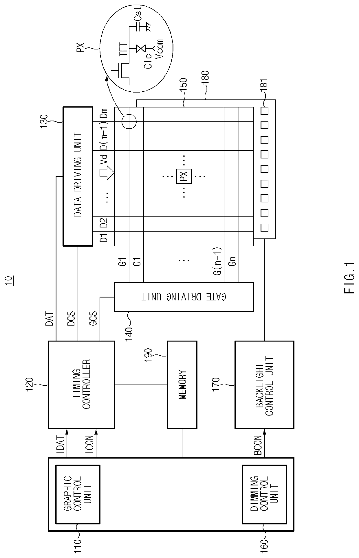
[0022]FIG. 1 is a block diagram illustrating a display device, according to an embodiment of the disclosure.

[0023]As illustrated in FIG. 1, according to an embodiment, a display device 10 may include a liquid crystal panel 150, a data driving unit 130, a gate driving unit 140, a graphic control unit 110, a dimming control unit 160, a memory 190, a timing controller 120, a backlight 180, and a backlight control unit 170. According to an embod...


PUM


Abstract

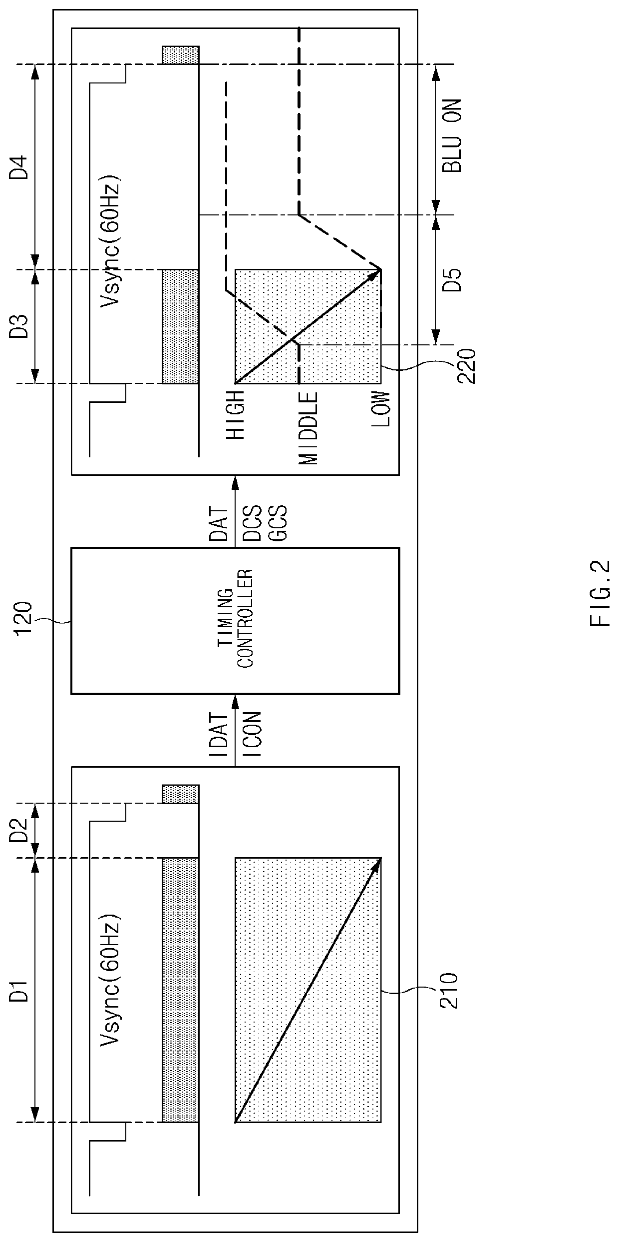
A display device according to one aspect of the disclosure includes a liquid crystal panel, a backlight including at least one light source to irradiate light to the liquid crystal panel, a timing controller to scan, in each frame period based on a synchronization signal which is input, the liquid crystal panel at a scan rate faster than a frame rate based on the synchronization signal, and a backlight control unit to turn on the backlight till a second time point, which is a scan time point of a next frame, from a first time point when a specified time elapses from a time point in which scan of the liquid crystal panel is finished in each frame period.

Description

[0001]This application is the U.S. national phase of International Application No. PCT / KR2017 / 007233 filed Jul. 6, 2017 which designated the U.S. and claims priority to KR Patent Application No. 10-2016-0140158 filed Oct. 26, 2016, the entire contents of each of which are hereby incorporated by reference.TECHNICAL FIELD[0002]Various embodiments in the disclosure relate to a display device and a display method, capable of improving Motion Blur of a liquid crystal display.DESCRIPTION OF RELATED ART[0003]A cathode ray tube (CRT) is an impulse-type display device to display data by light emitted by exciting a phosphor for a very short initial time in one period and to be in a stationary state for a remaining long time.[0004]To the contrary, a liquid crystal display may apply data to liquid crystal for a scanning duration (e.g., 80%) in which a scan voltage is applied and then may hold the applied data for a blank duration (e.g., 20%).[0005]In a hold-type device such as the liquid crysta...

Claims


Application Information

Patent Timeline
Patent Type & Authority Patents(United States)
IPC IPC(8): G09G3/36G09G3/34
CPCG09G3/36G09G3/3413G09G2310/0237G09G3/3406G09G3/3611G09G2340/0435G09G2320/106G09G2320/0257G09G2310/0251G09G3/3648G09G2310/08
Inventor LIM, SUNG JIN
Owner SAMSUNG ELECTRONICS CO LTD
Learn More