Electrical connection box
a technology of electrical connection box and connection plate, which is applied in the direction of electrical apparatus, connection, coupling device connection, etc., can solve the problems of bending of the top plate, insufficient support of the top plate of the cover, and insufficient support of the terminal portion of the electrical connection box, so as to prevent the deformation of the cover and the case from being further enhanced, smooth and stably inserted, the effect of improving the reliability of the connection
- Summary
- Abstract
- Description
- Claims
- Application Information
AI Technical Summary
Benefits of technology
Problems solved by technology
Method used
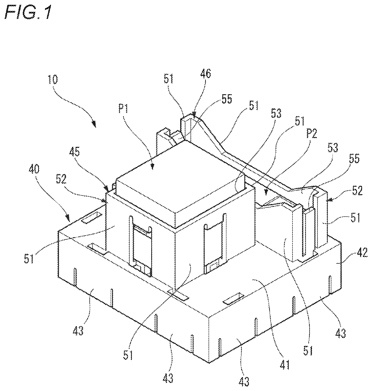
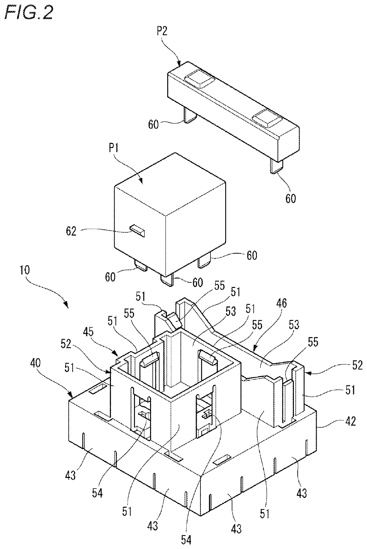
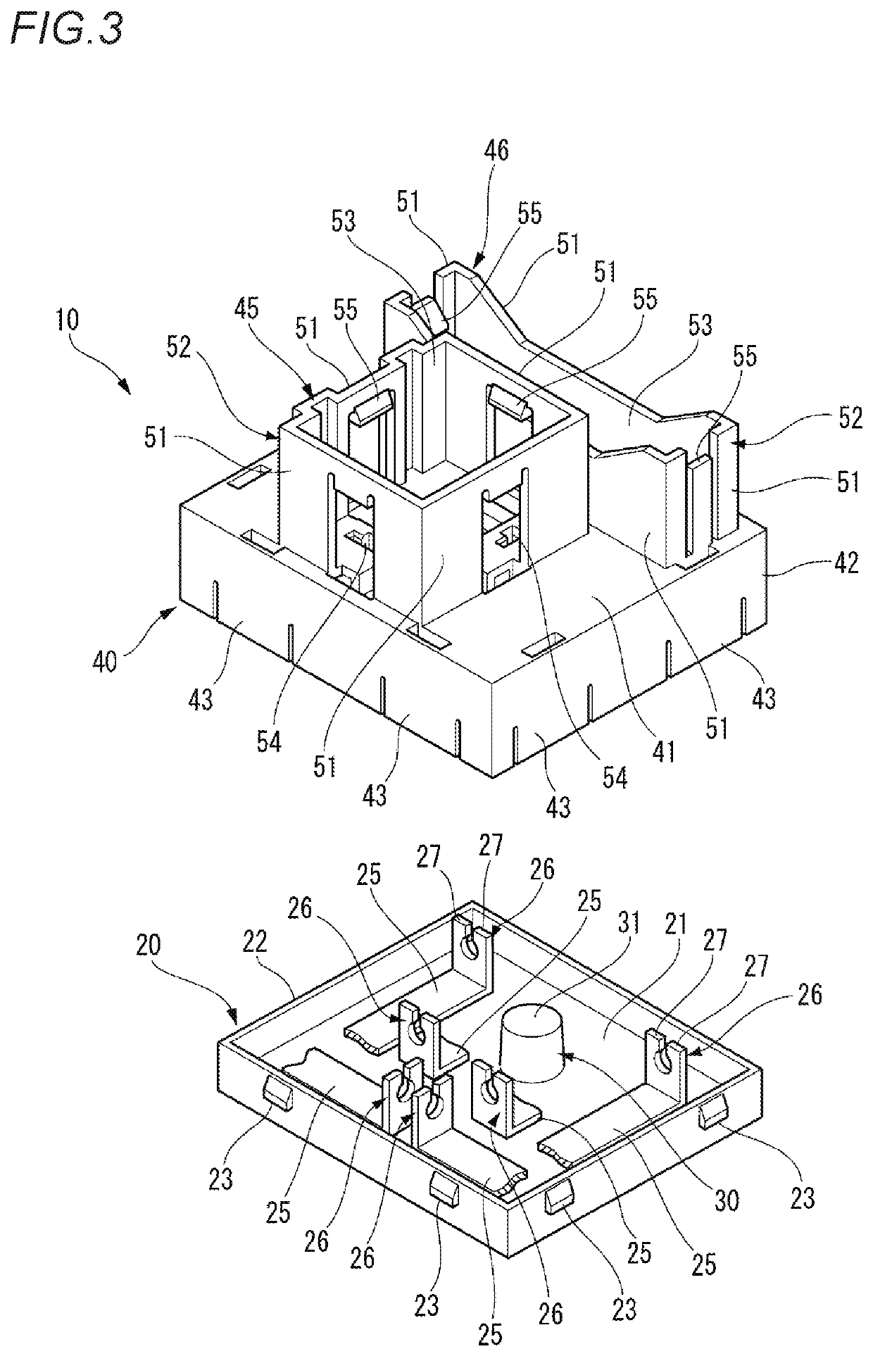
Image

Examples
first modification
(First Modification)
[0056]FIGS. 7A and 7B are views showing an internal structure of an electrical connection box according to a first modification, wherein FIG. 7A is a cross-sectional view taken along a line B-B in FIG. 5B, and FIG. 7B is a cross-sectional view taken along a line A-A in FIG. 5A.
[0057]As shown in FIGS. 7A and 7B, an electrical connection box 10A according to the first modification includes the same number of bosses 30 as that of the plurality of components P1, P2. These bosses 30 correspond to the component mounting portions 45, 46 on which the respective components P1, P2 are mounted and are provided on the case 20. Further, these bosses 30 are arranged respectively in ranges of the component mounting portions 45, 46 in the component mounting area PA in the plan view.
[0058]In the first modification, since the bosses 30 are arranged respectively in the ranges of the component mounting portions 45, 46 in the component mounting area PA in the plan view, when the comp...
second modification
(Second Modification)
[0059]FIG. 8 is a perspective view of an electrical connection box according to a second modification. FIGS. 9A and 9B are views showing the electrical connection box according to the second modification, wherein FIG. 9A is a plan view, and FIG. 9B is a side view. FIGS. 10A and 10B are views showing an internal structure of the electrical connection box according to the second modification, wherein FIG. 10A is a cross-sectional view taken along a line D-D in FIG. 9B and FIG. 10B is a cross-sectional view taken along a line C-C in FIG. 9A.
[0060]As shown in FIG. 8 and FIGS. 9A and 9B, an electrical connection box 10B according to the second modification is formed in an elongated shape in the plan view. In the electrical connection box 10B, two component mounting portions 45 each having a substantially square shape in the plan view are provided on the cover 40 with a gap interposed therebetween. In the electrical connection box 10B, the boss 30 corresponding to eac...
PUM
 Abstract
Description
Claims
Application Information
 - R&D
- Intellectual Property
- Life Sciences
- Materials
- Tech Scout
- Unparalleled Data Quality
- Higher Quality Content
- 60% Fewer Hallucinations
Browse by: Latest US Patents, China's latest patents, Technical Efficacy Thesaurus, Application Domain, Technology Topic, Popular Technical Reports.
© 2025 PatSnap. All rights reserved.Legal|Privacy policy|Modern Slavery Act Transparency Statement|Sitemap|About US| Contact US: help@patsnap.com