Ocular prosthesis with display device

a display device and ocular prosthesis technology, applied in the field of ocular prosthesis with display device, can solve the problems of limited or no movement, insecurity of patients, and inability to appear realistic, and achieve the effect of normal motility

Active Publication Date: 2020-11-03
MEMORIAL SLOAN KETTERING CANCER CENT
View PDF20 Cites 2 Cited by
  • Summary
  • Abstract
  • Description
  • Claims
  • Application Information

AI Technical Summary

Problems solved by technology

Current prosthetic eyes can have a good appearance in photographs, but have limited or no movement and therefore do not appear realistic when the patient attempts to move his or her eyes.
Therefore, such prostheses are a daily reminder of an obvious deformity and lead to insecurity of the patient, a reluctance to be seen in public, a feeling of inferiority, and unhappiness.
Over the years ophthalmic surgeons have tried many ways to create a prosthesis that moves, but such attempts have failed.
Many attempts to couple the ball and the prosthesis have been tried since the first ocular prosthesis was created just over 100 years ago; however, it is believed that all such attempts have failed to produce natural movement of the prosthesis.

Method used


Image

  • Ocular prosthesis with display device
  • Ocular prosthesis with display device
  • Ocular prosthesis with display device

Examples


Embodiment Construction

[0054]A method and apparatus are described for an ocular prosthesis with a display device. In the following description, for the purposes of explanation, numerous specific details are set forth in order to provide a thorough understanding of the present invention. It will be apparent, however, to one skilled in the art that the present invention may be practiced without these specific details. In other instances, well-known structures and devices are shown in block diagram form in order to avoid unnecessarily obscuring the present invention.

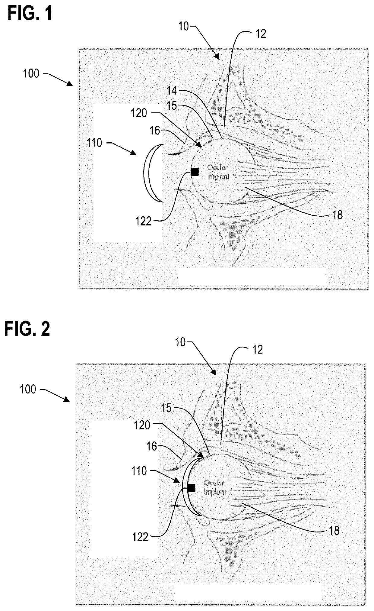
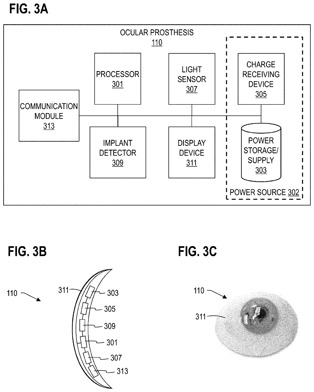
[0055]Some embodiments of the invention are described below in the context of a self-contained ocular prosthesis with an electronic display working in concert with a marker configured to move with an orbital implant. However, the invention is not limited to this context. In other embodiments some of the functions of the ocular prosthesis (such as power storage or data processing or ambient light detection or implant orientation detection or natur...


PUM


Abstract

An ocular prosthesis includes a display device visible at an anterior portion of the ocular prosthesis. The display device is configured to present a changeable image that represents a natural appearance and movement for a visible portion of an eyeball of a subject. A system includes, besides the ocular prosthesis, an implant marker configured to move with an orbital implant disposed in an eye socket of a subject. A method includes determining a change in orientation of an orbital implant in a subject and determining an update to a natural appearance for a visible portion of an eyeball for the subject based on the change in orientation of the orbital implant. The method also includes rendering an update to an image of the natural appearance for a display device disposed in an ocular prosthesis configured to be inserted in the subject anterior to the orbital implant.

Description

CROSS-REFERENCE TO RELATED APPLICATIONS[0001]This application claims benefit of Provisional Appln. 61 / 750,421, filed Jan. 9, 2013, under 35 U.S.C. § 119(e).BACKGROUND OF THE INVENTION[0002]Twelve thousand patients a year lose an eye in the U.S. from accidents, infections, cancer, congenital anomalies and advanced ocular conditions such as diabetes and glaucoma. It is estimated that a quarter of a million Americans already have prostheses, and millions are estimated to have such prostheses or are in need of such prostheses worldwide. An ocular prosthesis is generally a molded, painted methylmethacrylate device placed between the lids for people who have lost eyes. This plastic needs polishing and ultimately replacement about every five years. Conventional prostheses may have a colored outer surface that resembles the natural eye of the patient. Current prosthetic eyes can have a good appearance in photographs, but have limited or no movement and therefore do not appear realistic when...

Claims


Application Information

Patent Timeline
Patent Type & Authority Patents(United States)
IPC IPC(8): A61F2/14A61B5/00A61B5/11A61F2/48
CPCA61B5/11A61B5/6821A61F2/141A61F2002/482A61F2250/0096A61B2562/046A61B2562/0219A61B2560/0223A61F2250/0097A61F2230/0019A61B2562/0223A61F2/482
Inventor ABRAMSON, DAVIDBOHLE, III, GEORGE C.FRISCH, PAULMARR, BRIAN P.BOOTH, PAULBLACK, PHILIP C.KATZE, ALAN B.MOORE, JAMES G.
Owner MEMORIAL SLOAN KETTERING CANCER CENT
Why Eureka
Try Eureka