Method and system for pre-operative implant sizing

a pre-operative and implant technology, applied in the field of computer assisted surgery, can solve the problems of incorrect implant size planning, improper implant size planning,

Active Publication Date: 2020-11-10
ORTHOSOFT ULC
View PDF24 Cites 2 Cited by
  • Summary
  • Abstract
  • Description
  • Claims
  • Application Information

AI Technical Summary

Problems solved by technology

However, the various overlapping bone structures (e.g., the two condyles of the femur), and the difficulty in obtaining a precise lateral or anterior positioning of the imaging equipment relative to the bone, may af

Method used


Image

  • Method and system for pre-operative implant sizing
  • Method and system for pre-operative implant sizing
  • Method and system for pre-operative implant sizing

Examples


Embodiment Construction

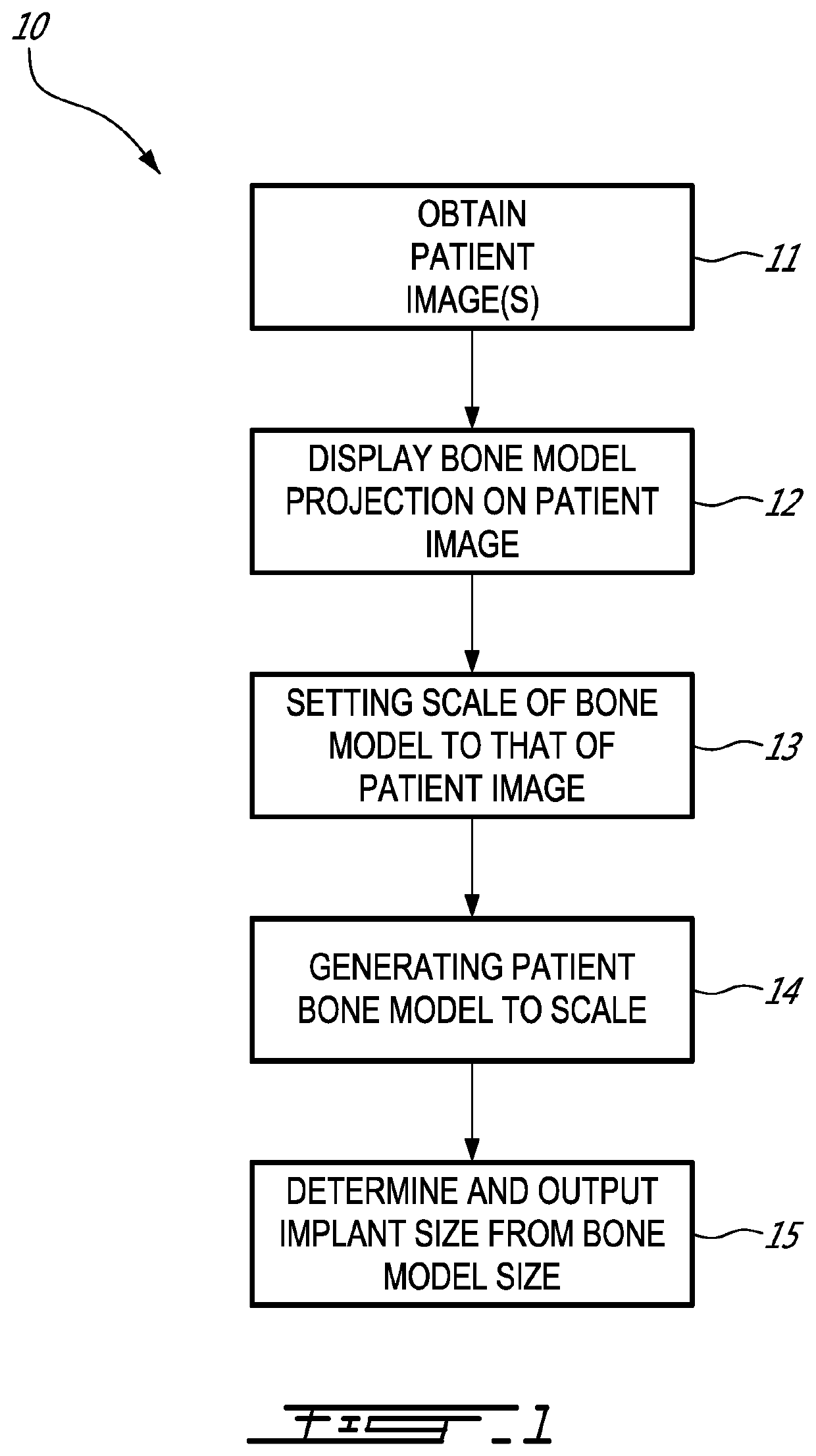
[0014]Referring to FIG. 1, a method for sizing implants pre-operatively is generally shown at 10. The method 10 is performed in pre-operative planning, i.e., before the commencement of surgery, for an operator to obtain an implant size or implant size range specific to the patient. Reference is made herein to an example featuring the knee femur. However, the method 10 can be used to size other implants, for example a tibia implant, shoulder implants, trauma hardware, etc. The method 10 may be of the type performed by one or more processor units. A non-transitory computer-readable memory may be communicatively coupled to the processing unit and comprising computer-readable program instructions executable by the processing unit for performing the method 10.

[0015]According to 11, one or more images of a bone are obtained, referred to herein as patient image(s), as the image(s) is patient specific. The patient image may be a projectional radiographic image (also known as X-ray image), a...


PUM


Abstract

A system for sizing an implant for a patient pre-operatively comprises a processor unit. A non-transitory computer-readable memory may be communicatively coupled to the processing unit and comprising computer-readable program instructions executable by the processing unit for obtaining at least one radiographic patient image of at least one patient bone with a scale marker relative to the bone, the scale marker having a known geometry, setting a scale of the at least one radiographic patient image using the known geometry of the scale marker, generating a three-dimensional bone model representative of the at least one patient bone using the at least one radiographic patient image and the scale, identifying an implant size and/or an implant model using implant models and dimensions of the three-dimensional bone model based on said scale, and outputting the implant size and/or the implant model for the patient.

Description

CROSS-REFERENCE TO RELATED APPLICATION[0001]The present application claims the priority of U.S. Patent Application No. 62 / 570,361, filed on Oct. 10, 2017 and incorporated herein by reference.FIELD OF THE APPLICATION[0002]The present application relates to computer-assisted surgery and, more particularly, to a pre-operative sizing of implants in the planning of surgery.BACKGROUND OF THE ART[0003]Radiographic imaging is commonly used to image bones and soft tissue, to detect pathologies and to plan for surgery. In particular, projectional radiography equipment may be more easily accessible than other imaging equipment. For instance, in knee orthopedic surgery, a femoral and / or tibial implant component are respectively implanted in the femur and tibia, at the knee, and the planning may often be performed using projectional X-ray images.[0004]The X-ray images are typically obtained in projectional radiography from a lateral point of view, and from an anterior point of view. Accordingly,...

Claims


Application Information

Patent Timeline
IPC IPC(8): A61B34/10A61B90/00
CPCA61B90/37A61B34/10A61B2034/108A61B2034/102A61B2034/105A61B2090/367A61B2090/3966A61B90/39A61B2034/254
Inventor MERETTE, JEAN-SEBASTIENCHAV, RAMNADA
Owner ORTHOSOFT ULC
Why Eureka
Try Eureka