
Method for producing at least one ash-forming means for a particulate filter of an exhaust gas system of a gasoline engine

a technology of exhaust gas system and ash-forming means, which is applied in the direction of machines/engines, separation processes, transportation and packaging, etc., to achieve the effect of clear correlation and low cos

Active Publication Date: 2020-11-10
DR ING H C F PORSCHE AG
View PDF4 Cites 0 Cited by
  • Summary
  • Abstract
  • Description
  • Claims
  • Application Information

AI Technical Summary

Benefits of technology

[0009]The method according to the invention makes particularly simple and inexpensive production of the at least one ash-forming means possible. The ash-forming means produced by the method can be arranged, for example, at an inlet of a particulate filter of an exhaust gas system of a gasoline / diesel engine or at an outlet or inlet of a catalytic converter of the exhaust gas system.
[0018]The ash-forming means produced by the above-described method has several advantages. For example, the ash can be applied precisely on the surface of the particulate filter. Additionally, the ash layer can be set precisely with regard to thickness and composition. Furthermore, the depth filtration is prevented in a targeted manner, and therefore a clear correlation between the counterpressure and the accumulated soot can be established. Still further, the filtration rate of prior art particulate filters assumes the desired value only after a certain running time. In contrast, the filtration rate reaches the required value by the use of the ash-forming means directly following the first heating operation of the exhaust gas system.

Problems solved by technology

The current statutory requirements for consumption reduction and the simultaneous tightening of the particulate limit values (mass and quantity) increasingly represent a challenge for the development of internal combustion engines.

Method used


Image

  • Method for producing at least one ash-forming means for a particulate filter of an exhaust gas system of a gasoline engine

Examples


Embodiment Construction

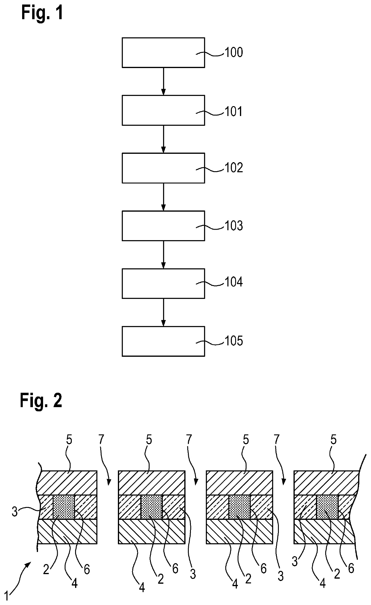
[0022]An ash-forming means 1 for a particulate filter of a gasoline engine or diesel engine has ash-forming components 2, as shown in FIG. 2. The ash-forming means 1 has a center layer 3, a bottom layer 4 and a top layer 5 that are connected to one another.

[0023]An ash-forming means 1 of this type is produced from a wafer in the method described in the following text. In a first step 100, a strip-shaped center layer 3 is provided and is produced from paper or cardboard. Receiving holes 6 for receiving the ash-forming components 2 are made in the center layer 3. The receiving holes 6 can be produced by punching in a particularly simple way. The shape of the receiving holes 6 can be selected in any desired way. For example, receiving holes can be circular, oval or polygonal.

[0024]In a second step 101, a bottom layer 4 is provided and also preferably is a strip produced from paper or cardboard. The bottom layer 4 is connected permanently to the center layer 3 in a suitable way, such as...


PUM

PropertyMeasurementUnit
massaaaaaaaaaa
permeabilityaaaaaaaaaa
pressureaaaaaaaaaa

Abstract

A method is provided for producing at least one ash-forming element (1) for a particulate filter of an exhaust gas system of a gasoline engine or diesel engine. The method includes providing of a strip-shaped center layer (3), and making receiving holes (6) in the center layer (3). The method continues by providing of a strip-shaped bottom layer (4), and permanently connecting of the bottom layer (4) to the center layer (3). The method proceeds by filling the receiving holes (6) of the center layer (3) with ash-forming components (2), providing a strip-shaped top layer (5), and permanently connecting the top layer (5) to the center layer (3). The method then includes punching out of at least one ash-forming means (1) from the wafer, and making throughflow openings (7) in regions where there are no ash-forming components (2).

Description

CROSS REFERENCE TO RELATED APPLICATION[0001]This application claims priority under 35 USC 119 to German Patent Appl. No. 10 2018 114 287.0 filed on Jun. 14, 2018, the entire disclosure of which is incorporated herein by reference.BACKGROUNDField of the Invention[0002]The invention relates to a method for producing at least one ash-forming means for a particulate filter of an exhaust gas system of a gasoline engine or diesel engine.Related Art[0003]The current statutory requirements for consumption reduction and the simultaneous tightening of the particulate limit values (mass and quantity) increasingly represent a challenge for the development of internal combustion engines. The adherence to future particulate limit values under the required boundary conditions will in future stand in the way of a consumption decrease. This leads to a necessity for almost all internal combustion engines to be equipped with a particulate filter in future, as already is the case for diesel engines.[00...

Claims


Application Information

Patent Timeline
Patent Type & Authority Patents(United States)
IPC IPC(8): B01D46/00B32B37/12B32B38/04F01N3/023B01D46/10B26F1/38B32B7/12B32B38/00F01N3/00B26F1/00B32B37/00B32B29/00
CPCB01D46/10B32B7/12B32B38/04B26F1/38F01N3/023B01D46/006B32B29/005B01D46/0001B32B37/12B32B2038/042B01D2279/30B32B2250/03B32B2250/26B32B2317/12B01D2275/10F01N3/021F01N3/022F01N3/033F01N3/0222F01N3/0232B32B27/10B32B2605/00B32B3/266F01N13/18F01N2330/04F01N2330/101F01N2450/28B01D46/80
Inventor ENGIN, LUKASWESSELS, MICHAEL
Owner DR ING H C F PORSCHE AG
Learn More