

Synchronization unit for a gear changing transmission
a gear changing transmission and synchronization unit technology, which is applied in the direction of mechanical actuating clutches, actuators, clutches, etc., can solve the problems of increased wear or abrasion costly coating of the tooth flanks, and limited effective surface for transferring force, etc., to achieve smooth engagement, simple production of the synchronization unit, and cost-effective
- Summary
- Abstract
- Description
- Claims
- Application Information
AI Technical Summary
Benefits of technology
Problems solved by technology
Method used
Image

Examples
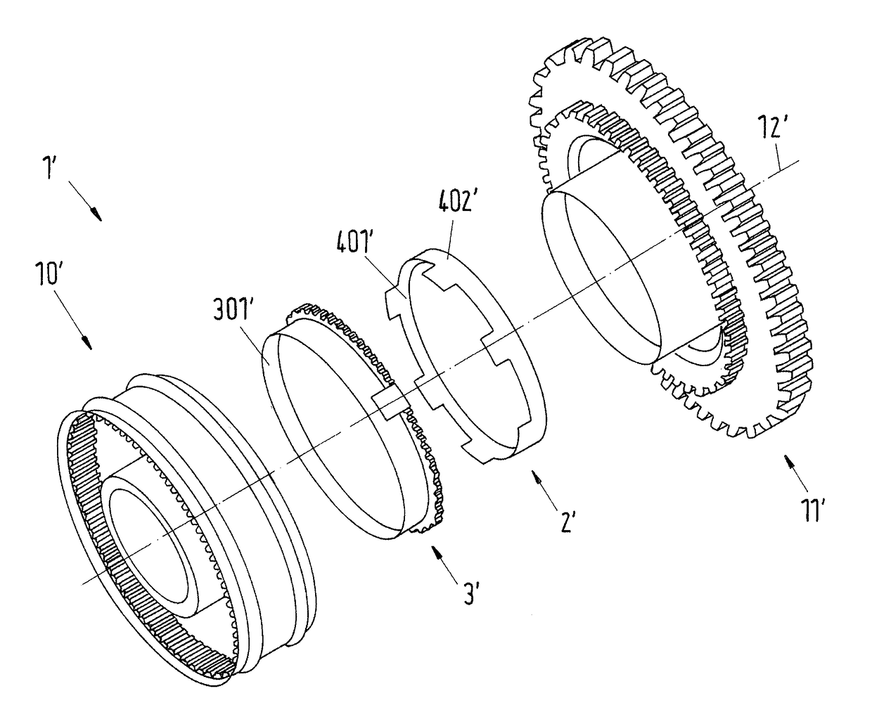
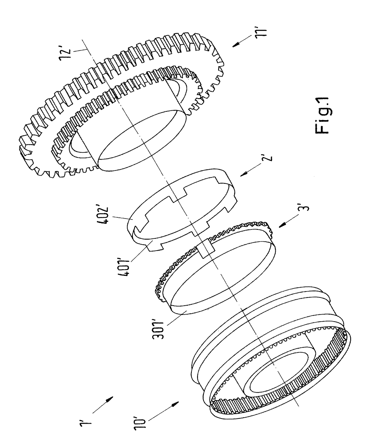
first embodiment
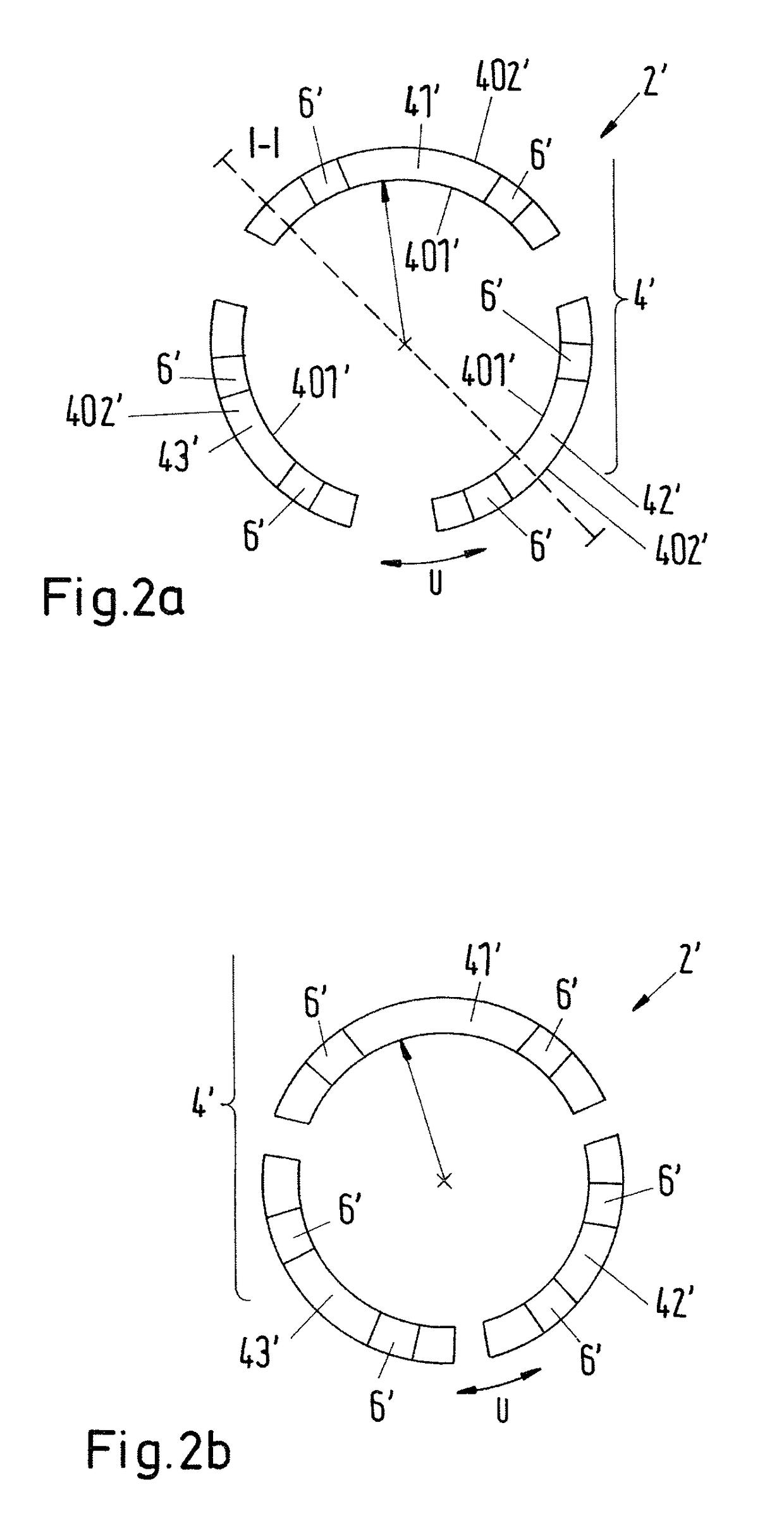
[0054]FIG. 2a shows a known segmented friction ring having axial securing means against rotation in an expanded configuration for a synchronization unit according to FIG. 1;
[0055]FIG. 2b shows the friction ring according to FIG. 2a in a compressed configuration;
[0056]FIG. 2c shows a section along the line I-I according to FIG. 2a;
[0057]FIG. 2d shows a section of the friction ring according to FIGS. 2a or 2b in a perspective view;
second embodiment
[0058]FIG. 3a shows a known segmented friction ring having radial securing means against rotation;
[0059]FIG. 3b shows a section of the friction ring according to FIG. 3a in perspective view;
[0060]FIG. 4a shows a perspective view of an embodiment of a synchronization unit according to the invention;
[0061]FIG. 4b shows a perspective view of a synchronizer ring according to the invention for a synchronization unit according to FIG. 4a;
[0062]FIG. 4c shows a perspective view of a friction ring according to the invention for a synchronization unit according to FIG. 4a;
[0063]FIG. 4d shows a schematic view of the profile of the friction ring according to FIG. 4c;
[0064]FIG. 4e shows a cross-section of the unit shown in FIG. 4a using a sectioning plane passing through the unit and perpendicular to the center axis;
[0065]FIG. 4f shows a perspective cross-section of the unit shown in FIG. 4a;
[0066]FIG. 5a shows a schematic view of a profile of a second embodiment of a friction ring according...
third embodiment
[0067]FIG. 5b shows a schematic view of a profile of a friction ring according to the invention;
PUM
 Abstract
Description
Claims
Application Information