Organic light-emitting diode display panel

a technology of light-emitting diodes and display panels, which is applied in the field of display technologies, can solve the problems of affecting the service life of the light-emitting device, etc., and achieves the effect of prolonging the display life of the oled display panel and negatively affecting the display quality of the entire panel

Active Publication Date: 2020-11-10
WUHAN CHINA STAR OPTOELECTRONICS TECH CO LTD
View PDF22 Cites 0 Cited by
  • Summary
  • Abstract
  • Description
  • Claims
  • Application Information

AI Technical Summary

Benefits of technology

[0005]The invention provides an OLED display panel, which is provided with a water blocking structure at the cutting position, which can perform a water blocking protection on the light-emitting device at the cutting position, thereby preventing the water vapor from penetrating into the OLED panel from the cutting position and causing damage to the light-emitting device, solving the technical problems that negatively affect display quality.
[0037]Compared with the existing organic light-emitting diode (OLED) display panel, the OLED display panel of the present invention is provided with a water blocking wall at the cutting position, which isolates the light-emitting device at the cutting position and the light-emitting device in the display area from the water vapor, thereby protecting the light-emitting device in the panel from water vapor intrusion, thus prolonging the display life of the OLED display panel. Therefore, the problems of the existing in-screen profile cutting technology can be solved, such as that the cut position is not protected by the encapsulation layer after the OLED display panel is cut, thereby exposing the light-emitting device, and the water vapor intrudes the OLED display panel from the cut position, causing damage to the light-emitting device, which in turn negatively affects the display quality of the entire panel.

Problems solved by technology

This process causes side surfaces of the EL and TFE layers to be directly exposed to the atmosphere, and water and oxygen may intrude from the side surfaces of the EL and TFE layers, seriously impacting on the service life of a light-emitting device.
In summary, in existing in-screen profile cutting technology, after an OLED display panel is cut, a cutting position is no longer protected by the encapsulation layer, thereby exposing the light-emitting device, and the water vapor may intrude the OLED panel from the cutting position, causing damage to the light-emitting device, thereby negatively affecting display quality of the entire panel.

Method used


Image

  • Organic light-emitting diode display panel
  • Organic light-emitting diode display panel
  • Organic light-emitting diode display panel

Examples


Embodiment Construction

[0046]The following description of the various embodiments is provided to illustrate the specific embodiments of the invention. The spatially relative directional terms mentioned in the present invention, such as “upper”, “lower”, “before”, “after”, “left”, “right”, “inside”, “outside”, “side”, etc. and the like, may be used herein for ease of description to describe one element or feature's relationship to another element(s) or feature(s) as illustrated in the figures which are merely references. The spatially relative terms are intended to encompass different orientations in addition to the orientation as depicted in the figures.

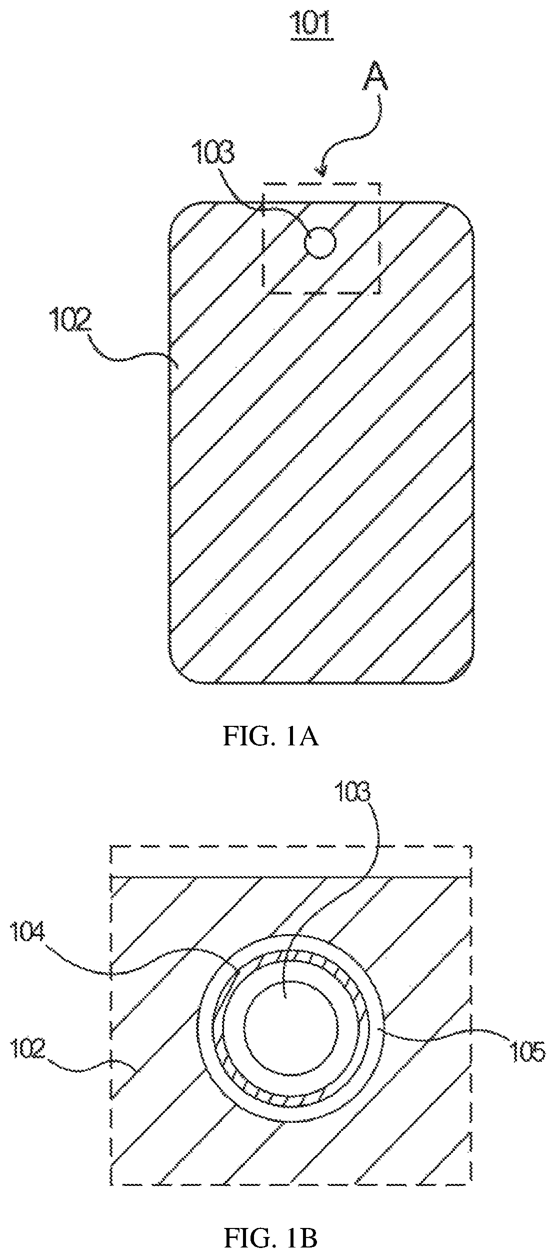
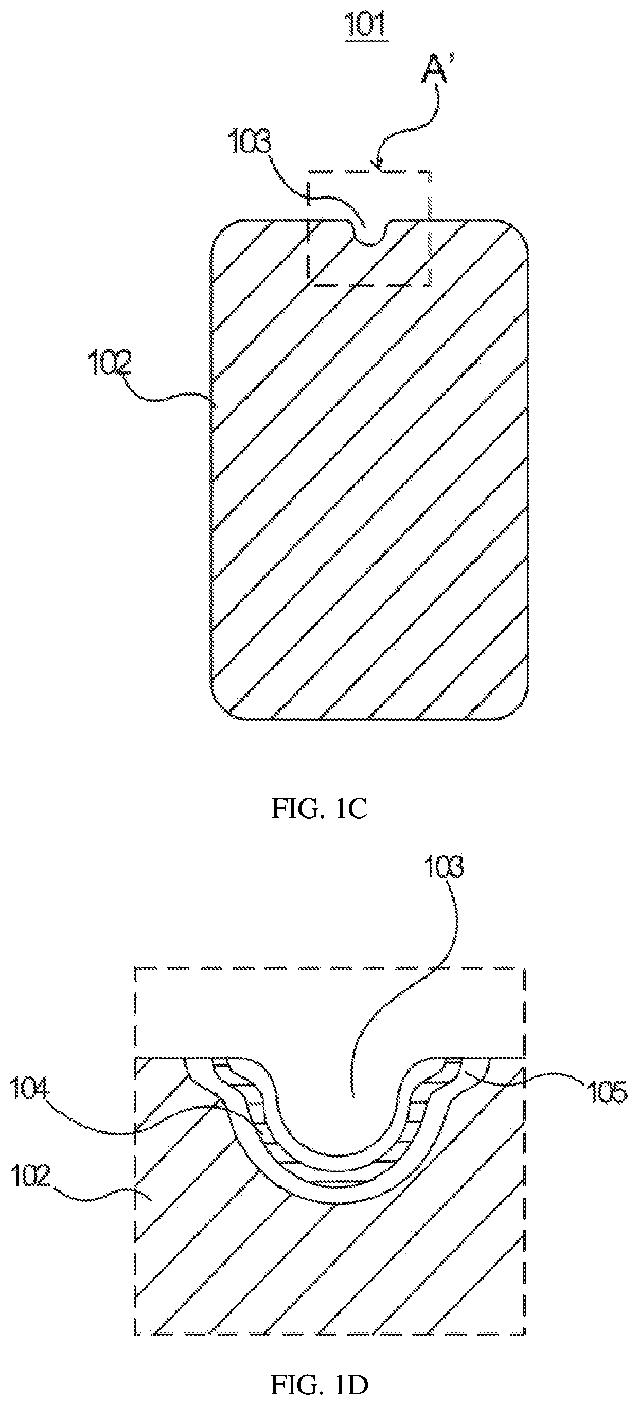
[0047]The invention is directed to solve the problems of the existing in-screen profile cutting technology, wherein after an organic light-emitting diode (OLED) display panel is cut, a cutting position is not protected by an encapsulation layer, thereby exposing a light-emitting device, and water vapor intrudes the OLED display panel from a cutting portion...


PUM

PropertyMeasurementUnit
angleaaaaaaaaaa
areaaaaaaaaaaa
contour shapeaaaaaaaaaa

Abstract

The present invention provides an organic light-emitting diode (OLED) display panel, wherein a display area of the OLED display panel is formed with a via hole and a water blocking structure for protecting the via hole from water vapor. The water blocking structure includes at least one trench defined in a surface of the substrate, and a baffle wall formed in the trench, and a top of the baffle wall is higher than an OLED emitting layer.

Description

BACKGROUND OF INVENTIONField of Invention[0001]The present invention relates to the field of display technologies, and in particular, to an organic light-emitting diode (OLED) display panel.Description of Prior Art[0002]Flexible organic light-emitting diodes (OLEDs) are deformable and flexible display devices, having advantages of self-illumination, wide viewing angles, high contrast, low power consumption, fast response times, etc, compared with traditional rigid displays. OLED luminescent materials are organic materials extremely sensitive to water and oxygen. Generally, flexible OLEDs adopt thin film encapsulation (TFE) technology and an encapsulation layer is generally a multilayered structure composed of stacked inorganic / organic / inorganic layers, wherein water vapor transmission permeance (WVTR) can be reduced to a level about 10-6 g / m2·day to ensure normal operation of OLED luminescent materials.[0003]In preparation of an in-screen O-cut display screen, it is necessary to ope...

Claims


Application Information

Patent Timeline
Patent Type & Authority Patents(United States)
IPC IPC(8): H01L51/52H01L27/32H01L51/00
CPCH01L27/32H01L51/5256H01L51/0096H01L2251/53Y02E10/549H10K50/844H10K50/8445H10K59/00H10K77/10H10K2102/302
Inventor SHI, JIE
Owner WUHAN CHINA STAR OPTOELECTRONICS TECH CO LTD
Why Eureka
Try Eureka