Demodulator/detector for digital isolators

a demodulator and digital isolator technology, applied in the field of isolation technology, can solve the problems of asymmetric propagation delay, requiring isolation barrier, and conventional demodulator techniques having substantial propagation delay and/or asymmetric propagation delay

Active Publication Date: 2020-11-17
SKYWORKS SOLUTIONS INC
View PDF11 Cites 9 Cited by
  • Summary
  • Abstract
  • Description
  • Claims
  • Application Information

AI Technical Summary

Benefits of technology

[0007]In at least one embodiment of the invention, a receiver signal path includes a high pass filter configured to center a received differential pair of signals around a common mode voltage to generate a centered received differential pair of signals. The receiver signal path includes a demodulator configured to remove a carrier signal from the centered receiv...

Problems solved by technology

During normal operation, a large DC or transient voltage difference may exist between the power domain of the processor system and the power domain of the load system, thus requiring a...

Method used


Image

  • Demodulator/detector for digital isolators
  • Demodulator/detector for digital isolators
  • Demodulator/detector for digital isolators

Examples


Embodiment Construction

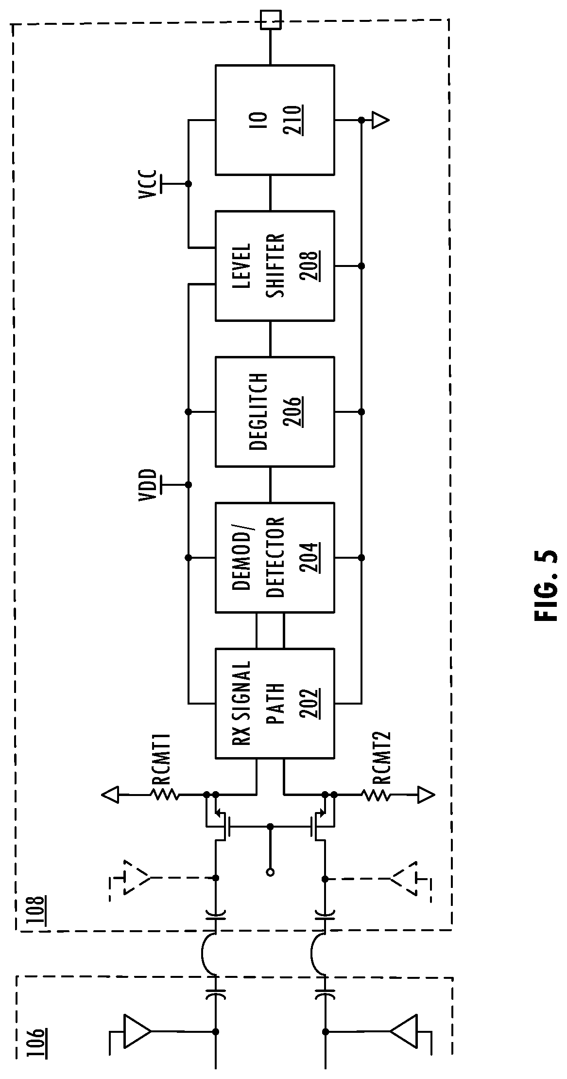
[0005]In at least one embodiment of the invention, a receiver signal path includes a high pass filter configured to center a received differential pair of signals around a common mode voltage to generate a centered received differential pair of signals. The receiver signal path includes a demodulator configured to remove a carrier signal from the centered received differential pair of signals to generate a demodulated signal and configured to generate a logic signal based on the demodulated signal and a predetermined threshold signal. The demodulator includes a differential stage. The differential stage includes an extremum selector circuit configured to generate the demodulated signal based on the centered received differential pair of signals. The demodulated signal corresponds to a mean level of the rectified version of the centered received differential pair of signals. The differential stage includes a second circuit configured to provide the reference signal based on the prede...


PUM


Abstract

A receiver signal path includes a high pass filter that centers a received differential pair of signals around a common mode voltage to generate a centered received differential pair of signals. The receiver signal path includes a demodulator that removes a carrier signal from the centered received differential pair of signals to generate a demodulated signal and generates a logic signal based on the demodulated signal and a predetermined threshold signal. The demodulator includes a differential stage including an extremum selector circuit that generates the demodulated signal based on the centered received differential pair of signals. The demodulated signal corresponds to a mean level of the rectified version of the centered received differential pair of signals. The differential stage includes a second circuit that provides the reference signal based on the predetermined threshold signal. The logic signal is based on a comparison of the demodulated signal to the reference signal.

Description

RELATED APPLICATIONS[0001]This application is related to U.S. patent application Ser. No. 16 / 528,065, entitled “RECEIVER FRONT END FOR DIGITAL ISOLATORS,” naming Mohammad Al-Shyoukh as inventor, filed the same day as the present application, and is related to U.S. patent application Ser. No. 16 / 528,059, entitled “RECEIVER INTERMEDIATE VARIABLE GAIN STAGE FOR ISOLATOR PRODUCTS,” naming Mohammad Al-Shyoukh as inventor, filed the same day as the present application, and is related to U.S. patent application Ser. No. 16 / 528,256, entitled “CALIBRATION OF DIGITAL ISOLATORS”, naming Mohammad AI-Shyoukh and Peter Onody as inventors, filed the same day as the present application, all of which applications are incorporated herein by reference in their entirety.BACKGROUNDField of the Invention[0002]The invention relates to isolation technology and more particularly to an isolation product including a communications channel across an isolation barrier.Description of the Related Art[0003]In a ty...

Claims


Application Information

Patent Timeline
IPC IPC(8): H04B1/16H03F3/30H03H7/01H04L27/06
CPCH03F3/3001H04B1/16H03H7/0161H04L27/06H03D1/18H03F3/303H03F3/45188H03F3/45192H03F3/45475H03F2200/405H03F2203/45306H03F2203/45318
Inventor AL-SHYOUKH, MOHAMMAD
Owner SKYWORKS SOLUTIONS INC
Why Eureka
Try Eureka