Tube clamp and volumetric pump comprising tube clamp

a tube clamp and volumetric pump technology, applied in the field of medical tube clamps, can solve the problems of impede the optical or acoustic check of the safe snap fit of the closure system, difficult and cost-intensive manufacturing of tube clamps with constant exactly identical tolerances, and achieve the effect of facilitating the handling of the volumetric pump

Active Publication Date: 2020-11-24
B BRAUN MELSUNGEN AG
View PDF12 Cites 0 Cited by
  • Summary
  • Abstract
  • Description
  • Claims
  • Application Information

AI Technical Summary

Benefits of technology

[0006]Therefore, it is an object of the invention to avoid or at least to alleviate the drawbacks from the state of the art and to provide ways and means for enabling an increase in the operating safety of a tube clamp as well as of a volumetric pump. A preferred objective of the present invention resides in rendering insertion and clamping of a flexible medical tube in a tube clamp and in a volumetric pump safer and easier.
[0008]Basically, the present invention provides a (partial) uncoupling and, respectively, an elastically / resiliently movable coupling between the clamping portion and the clamping jaw via the connecting member. A constructional design of the tube clamp helps to realize the at least one connecting member which in the case of flux of force is connected in series between the first clamping jaw and the second clamping jaw. In this way, with an overall consideration of the flux of force, elasticity can be adjusted between the two clamping jaws, whereas the two clamping portions are configured to be rigid, when considered relative thereto, and primarily in combination with the closure system serve for safe positioning relative to each other. Such constructional design of the tube clamp helps to absorb especially force peaks and to safely fix the two clamping portions relative to each other. The risk of inadvertent release of the positioning and, respectively, of the clamping snap-fit position is largely suppressed.
[0009]The tube clamp according to aspects of the invention facilitates, by the (partial) uncoupling and, respectively, elastic coupling of the clamping jaw and the clamping portion and thus the (partial) uncoupling of the closing mechanism (including the two clamping portions and the closure system) and the clamping mechanism (clamping jaws), the tube clamp to be completely locked and, respectively, brought into the clamping snap-fit position even more safely and easily with even more independence of the inserted medical tube and of the clamping mechanism.
[0015]Preferably, the first clamping jaw and / or the second clamping jaw may be in the form of a clamping edge (having a linear geometric shape) the longitudinal axis (the longitudinal clamp axis / the longitudinal clamp direction) of which extends transversely to the longitudinal axis of the inserted medical tube (the longitudinal tube axis). Such clamping edge / clamping blade / clamping wedge is adapted to pinch off the medical tube in an optimally sealing manner without damaging the same.
[0018]It is of advantage when the first clamping portion, the connecting member and the first clamping jaw are formed of one material (are one piece of material) and / or the second clamping portion, the connecting member and the second clamping jaw are formed of one material (are one piece of material). Especially preferred, the entire medical tube clamp including the hinge is formed of one material (is one piece of material). Especially preferred, the tube clamp may be made from synthetic material and, further preferred, may be configured as a (thermoplastic) injection-molded part made from one material in which both the connecting members and the hinge are integrally incorporated or, respectively, are formed by specific material recesses in a tube clamp wall surface.
[0020]Another independently claimed aspect of the invention relates to a generic volumetric pump, especially an infusion pump, for delivering a medium through a flexible medical tube, comprising a housing, wherein, according to aspects of the invention, a medical tube clamp according to aspects of the invention is, preferably detachably, mounted on the housing for sealingly pinching (off) the medical tube. By using a medical tubing clamp according to aspects of the present invention, a safer and easier way of handling the volumetric pump can be achieved.

Problems solved by technology

In the state of the art, a problem will arise when the clamp is closed.
Also, it is difficult and cost-intensive to manufacture the tube clamp with constantly exactly identical tolerances.
On the one hand, said force peak requires great effort of operating staff members for closing the tube clamp and moreover constitutes a high safety risk, as the snap-fit closure system will not completely snap fit in an unfavorable case and may inadvertently come loose again so that a dangerous “free-flow situation” may inadvertently occur.
In addition, there are infusion pumps having tube clamps which automatically close the tube clamp via a pivoted door, which further impedes optical or acoustic check of safe snap fit of the closure system.

Method used


Image

  • Tube clamp and volumetric pump comprising tube clamp
  • Tube clamp and volumetric pump comprising tube clamp
  • Tube clamp and volumetric pump comprising tube clamp

Examples


Embodiment Construction

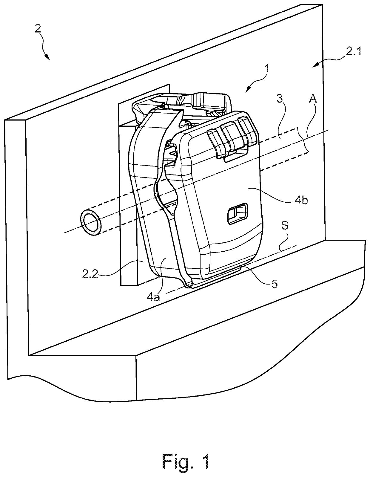
[0029]FIG. 1 schematically shows a perspective view of a medical tube clamp 1 according to aspects of the invention, more exactly speaking an infusion tube clamp 1 of a first preferred embodiment which is inserted in a volumetric pump 2 according to aspects of the invention in the form of an infusion pump 2 (here schematic partial view) with a dedicated housing 2.1. A flexible medical tube 3 (here schematic partial view) in the form of an infusion tube 3 is received in the infusion tube clamp 1 by clamping snap-fit (clamping snap-fit position). The schematically shown infusion pump 2 is a pump having a slide peristalsis in which the infusion tube 3 connecting a patient to an active agent reservoir (not shown) is placed upstream of the peristaltic slides (not shown) arranged in a tube insertion opening closable by a pump flap (not shown). The pump flap is subsequently closed and serves as a counter-bearing for the peristaltic slides pushing a volume inside the flexible infusion tube ...


PUM


Abstract

A medical tube clamp for clamping a flexible medical tube comprising: a tube receiving area which is adapted to receive the medical tube, a first clamping portion including a first clamping jaw which is movable relative to a second clamping portion including a second clamping jaw, and a closure system for safely positioning the two clamping portions in more than one snap-fit position relative to each other so that, when the closure system is unlocked, the medical tube can be inserted in and removed from the tube clamp, in an open snap-fit position the inserted medical tube cannot be removed and is not clamped and in a clamping snap-fit position the medical tube is clamped between the first clamping jaw and the second clamping jaw, with the first clamping jaw being configured to be elastically movable relative to the first clamping portion via a connecting member and / or the second clamping jaw being configured to be elastically movable relative to the second clamping portion via a connecting member. In addition, the invention relates to a volumetric pump.

Description

CROSS REFERENCE TO RELATED APPLICATIONS[0001]This application claims priority to German Patent Application No. DE 10,2017 / 122,647.8 filed Sep. 28, 2017, the contents of such application being incorporated by reference herein.FIELD OF THE INVENTION[0002]The present invention relates to a medical tube clamp, especially an infusion tube clamp, for (sealingly) clamping and, respectively, pinching off a flexible medical tube, especially an infusion tube specifically for use in an infusion pump, comprising a tube receiving area adapted to receive the medical tube, a first clamping portion (upper shell) including a first clamping jaw which is movable relative to a second clamping portion (lower shell) including a second clamping jaw, and a closure system for safely positioning the two clamping portions in more than one snap-fit position relative to each other so that in an unlocked inserting position of the two clamping portions the medical tube and, respectively, a tube portion hereof (wi...

Claims


Application Information

Patent Timeline
Patent Type & Authority Patents(United States)
IPC IPC(8): A61M39/28A61M5/168A61M5/142
CPCA61M5/142A61M39/286A61M39/284A61M5/16813A61M2205/3334A61M39/28A61M5/168
Inventor KRAMER, MATTHIASJACOBSKÖTTER, SARAHSTEGER, JÜRGENFREIGANG, HELMUTSCHRÖDL, CHRISTIANBATZDORF, STEFAN
Owner B BRAUN MELSUNGEN AG
Why Eureka
Try Eureka