
Floorplan visualisation system

a visualisation system and floor plan technology, applied in the field of floor plan visualisation system, can solve the problems of insufficient use of virtualisation software and difficulty in making such adjustments on paper format, and achieve the effect of accurate gauge the feel and therefore appropriateness

Active Publication Date: 2020-12-08
GHALEB CHRISTOPHER
View PDF16 Cites 9 Cited by
  • Summary
  • Abstract
  • Description
  • Claims
  • Application Information

AI Technical Summary

Benefits of technology

The invention is about a computer system that can display a floor plan at a real size, allowing users to better see and feel the layout. This makes it easier for buyas and other guests to determine if the floor plan is suitable for their needs. Physical objects can also be placed on the floor for inspection.

Problems solved by technology

However, it is difficult to make such adjustments on paper format and sophisticated architectural 3D rendering software may be used not only to place the proposed installations but also provide a virtualisation of the interior.
However, utilisation of virtualisation software is not always adequate for determining the appropriateness of a layout or for making adjustments accordingly.

Method used


Image

  • Floorplan visualisation system
  • Floorplan visualisation system

Examples


embodiments

[0116]Reference throughout this specification to “one embodiment” or “an embodiment” means that a particular feature, structure or characteristic described in connection with the embodiment is included in at least one embodiment of the present invention. Thus, appearances of the phrases “in one embodiment” or “in an embodiment” in various places throughout this specification are not necessarily all referring to the same embodiment, but may. Furthermore, the particular features, structures or characteristics may be combined in any suitable manner, as would be apparent to one of ordinary skill in the art from this disclosure, in one or more embodiments.

[0117]Similarly it should be appreciated that in the above description of example embodiments of the invention, various features of the invention are sometimes grouped together in a single embodiment, figure, or description thereof for the purpose of streamlining the disclosure and aiding in the understanding of one or more of the vario...


PUM


Abstract

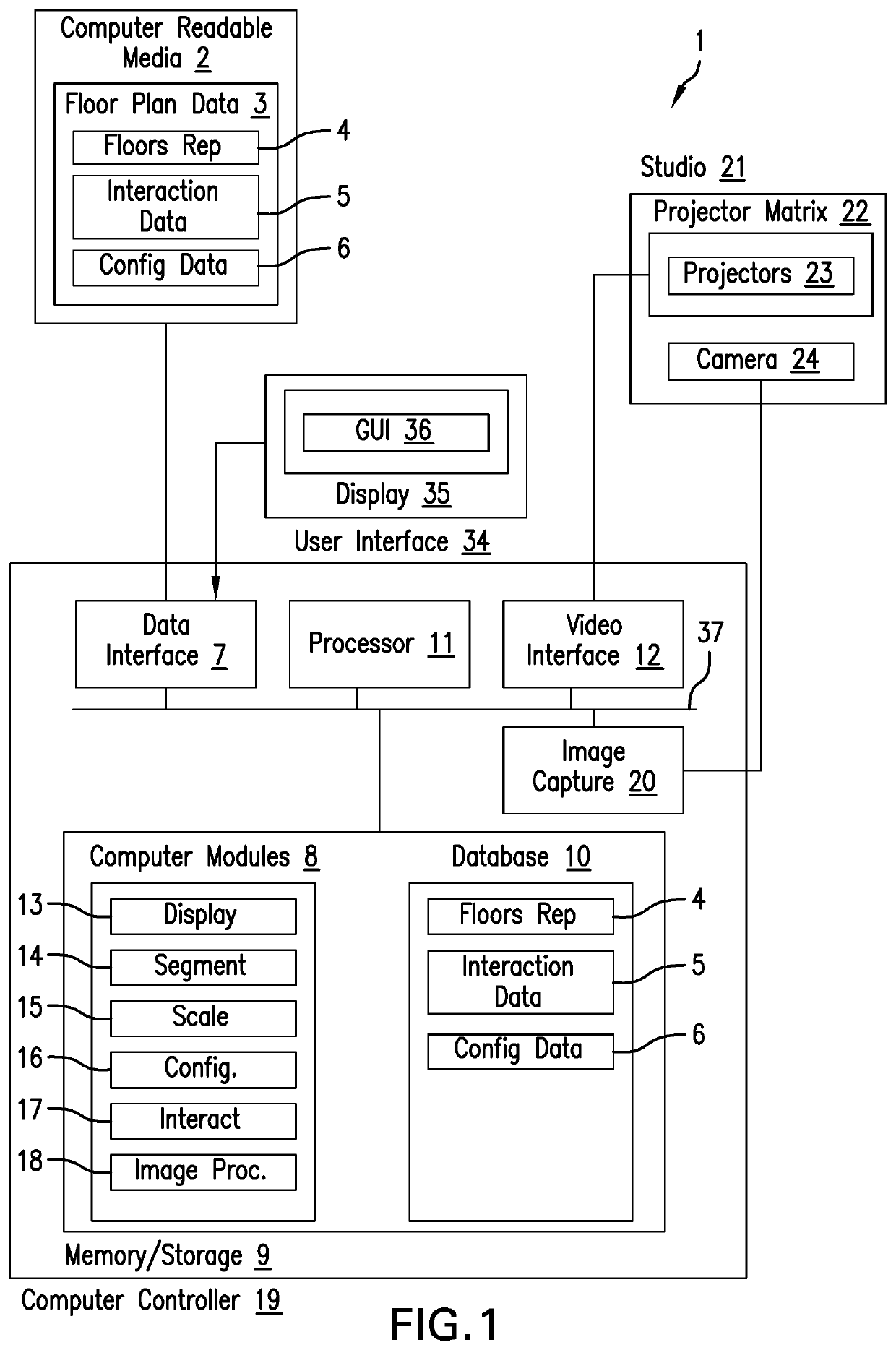
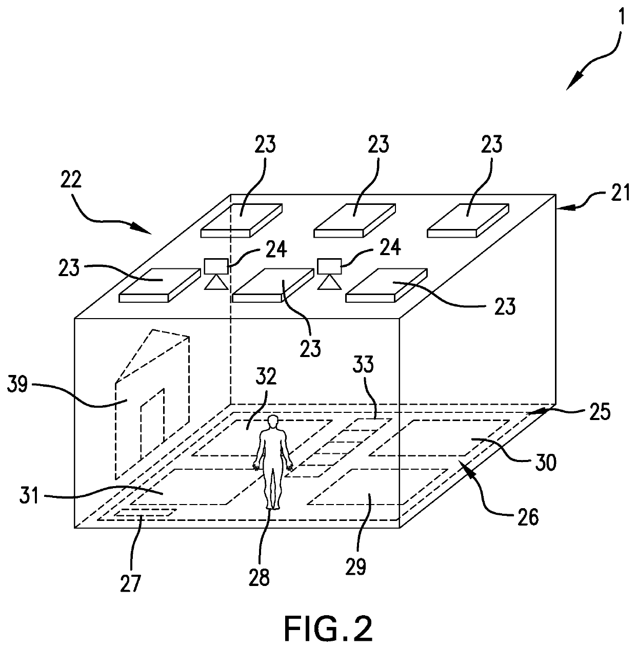
There is provided a floorplan visualisation system comprising a visualisation studio; a matrix of ceiling mounted edge-blended overlapping projectors projecting onto a floor surface of the visualisation studio; a controller computer comprising: a user interface; and a video output operably coupled to the matrix of projectors for controlling the video projected from such. In use the controller computer is configured for: receiving floor plan representative data; segmenting the floor plan representation data into a plurality of display segments; and outputting the plurality of display segments to respective projectors, and wherein the controller computer is configured to receiving scale adjustment commands via a scale adjustment control of the user interface and adjusting the scale of the segments to display a floor plan representation on the floor surface to a real world scale.

Description

FIELD OF THE INVENTION[0001]The present invention relates to a floorplan visualisation system.DETAILED DESCRIPTION[0002]Residential and / or commercial buildings and the like are built from floorplans which are drafted, inspected, and, if necessary adjusted prior building.[0003]The floorplans are typically prepared according to a scale so as to allow the representation on A3 page format for example.[0004]Prior construction, the floorplans are inspected and adjustments made accordingly. For example, the floorplans may be adjusted with reference to proposed furniture, appliances and / or other installations and according to the “feel” of the interior.[0005]However, it is difficult to make such adjustments on paper format and sophisticated architectural 3D rendering software may be used not only to place the proposed installations but also provide a virtualisation of the interior.[0006]However, utilisation of virtualisation software is not always adequate for determining the appropriatenes...

Claims


Application Information

Patent Timeline
Patent Type & Authority Patents(United States)
IPC IPC(8): G09G5/00G06F3/01G06T19/00G03B37/04G06K9/00G06T7/20G06F30/13G06Q50/08G03B21/14
CPCG06T19/006G06T7/20G06F3/017G06Q50/08G06K9/00335G03B37/04G06F30/13G03B21/14G06F3/011H04N9/3147H04N9/3194G06V40/20
Inventor GHALEB, CHRISTOPHER
Owner GHALEB CHRISTOPHER
Learn More