
Tibial fixation plate

a bone fixation plate and tibial technology, applied in the field of bone fixation plates, can solve the problems of restricting the ability to manipulate the bone plate on the bone, limiting the ability to implement the skin retractor, and conventional bone fixation plates not allowing such proximally high curvilinear cuts

Active Publication Date: 2020-12-15
STERIS INSTR MANAGEMENT SERVICES INC
View PDF48 Cites 1 Cited by
  • Summary
  • Abstract
  • Description
  • Claims
  • Application Information

AI Technical Summary

Benefits of technology

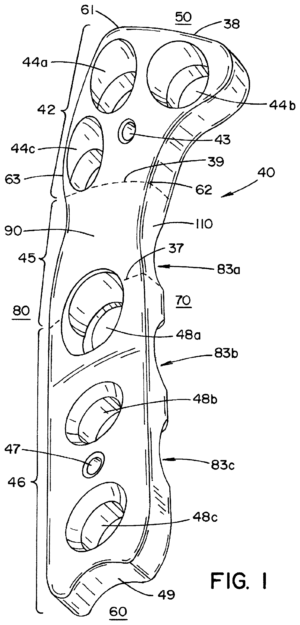
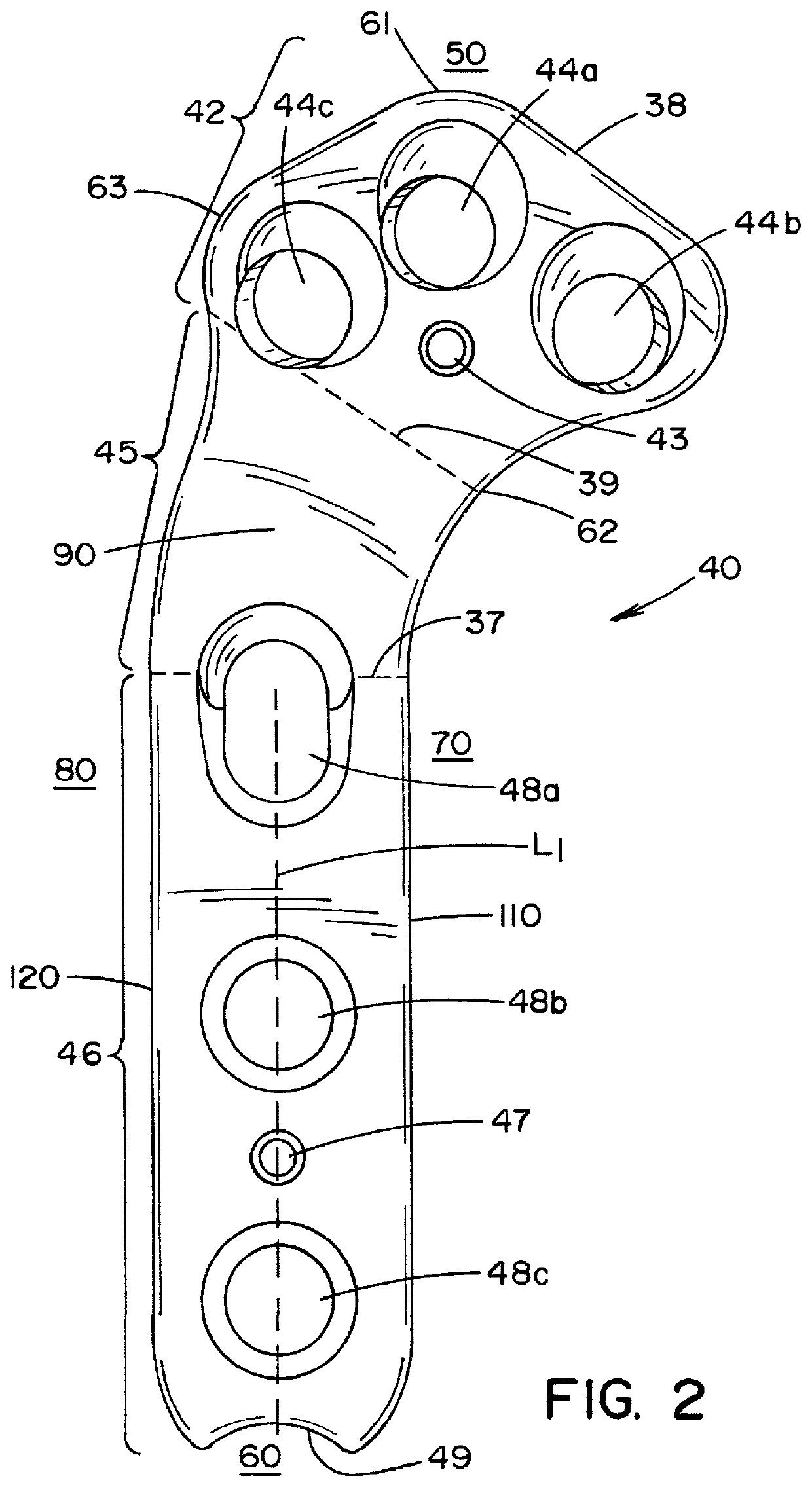
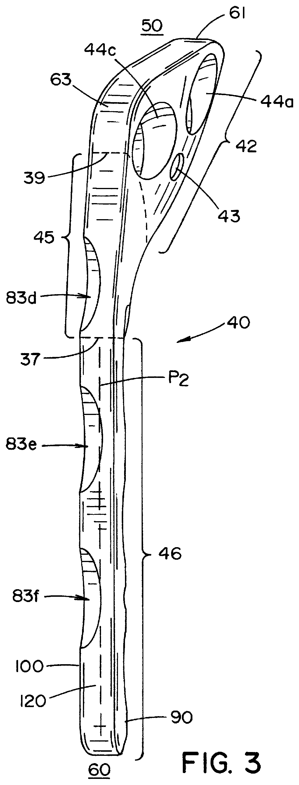
This invention is a bone fixation plate that has several advantages. First, it allows for a high quality cut of the muscle bone closest to a joint using the plate. Second, it allows for precise fitting of the plate to the bone by contouring the head section. Third, it allows for a secure purchase in an osteotomy where the head and tail sections of the plate make a significant connection. Fourth, it allows for 15 degrees of angulation between the plate and the bone through its apertures. Fifth, it prevents screws from entering the joint or bone at damaging angles through these apertures. Overall, the invention improves the accuracy and stability of bone fixation procedures.

Problems solved by technology

However, conventional bone fixation plates do not allow such proximally high curvilinear cuts to occur.
Further, the large size of head portions and hole locations restricts the ability to manipulate the plate on the bone.
Moreover, conventional bone fixation plates do not allow a place for implementation of a skin retractor.
As a result, the incisions required when utilizing a conventional bone fixation plate are long.
Finally, conventional bone fixation plates have screw holes that limited or restrictive as to how they allow screws inserted therein to be oriented.
In other words, the conventional bone fixation plates do not allow for polyaxial placement of the screws.

Method used


Image

  • Tibial fixation plate
  • Tibial fixation plate
  • Tibial fixation plate

Examples


Embodiment Construction

[0029]It is initially noted that, in the embodiments described herein, the standard anatomical terminology used corresponds to the standard anatomical position of a canine or an animal having hind limb anatomy corresponding with that of a canine. Application of the invention embodiments described herein is not restricted to a canine or an animal having hind limb anatomy corresponding with that of a canine. However, while it is contemplated that the invention could be applied to a human or an animal having lower leg anatomy corresponding with that of a human, the standard anatomical position of a human is different from the standard anatomical position of a canine. Thus, the standard anatomical terminology describing the application of the invention with respect to a canine or an animal having hind limb anatomy corresponding with that of a canine will not correspond to the standard anatomical terminology necessary to describe application of the invention with respect to a human or an...


PUM


Abstract

A fixation plate includes a head section, a curved section, and a tail section. The head section includes one or more head apertures formed therethrough. The head apertures are configured to allow screws to respectively pass therethrough at varying angles to attach the head section to a first bone segment. The head section has a bottom surface that is configured to sit flush with the first bone segment. The curved section extends from the head section. The tail section extends from the curved section. The tail section includes one or more tail apertures formed therethrough. The tail apertures are configured to allow screws to respectively pass therethrough at varying angles to attach the tail section to a second bone segment.

Description

FIELD OF THE INVENTION[0001]The present invention relates generally to a bone fixation plate and, more particularly, to a plate configured to fix a tibia in animals, including canines.BACKGROUND OF THE INVENTION[0002]Bone fixation plates may be used in tibial osteotomy and other procedures to secure two bone segments together. In a tibial plateau leveling osteotomy procedure, for example, a curvilinear cut is made in the canine proximal tibia to separate the metaphysis from the proximal tibia. Next, the metaphysis is rotated to level the tibial plateau. Finally, the metaphysis is fixed to the proximal tibia by a fixation plate.[0003]It is commonly desired by those performing a tibial osteotomy to make the curvilinear cut as proximally high and close to the joint between the tibia and the metaphysis as possible. However, conventional bone fixation plates do not allow such proximally high curvilinear cuts to occur. These proximally high curvilinear cuts are discouraged at least partia...

Claims


Application Information

Patent Timeline
Patent Type & Authority Patents(United States)
IPC IPC(8): A61B17/80
CPCA61B17/8061A61B17/8057A61B2090/3966
Inventor WOTTON, III, HAROLD M.KAZANOVICZ, ANDREW JAMESBARNHART, MATTHEW DUBOIS
Owner STERIS INSTR MANAGEMENT SERVICES INC
Learn More