
Rib arrangement in a wing tip device

a technology of wing tip and rib arrangement, which is applied in the direction of airflow influencers, heat reducing structures, spars/stringers, etc., can solve the problems of presenting a number of design obstacles, relatively complex structures of wing tip devices to design and build, etc., and achieves the effect of increasing the stiffness of the wing tip devi

Active Publication Date: 2020-12-15
AIRBUS OPERATIONS LTD
View PDF9 Cites 0 Cited by
  • Summary
  • Abstract
  • Description
  • Claims
  • Application Information

AI Technical Summary

Benefits of technology

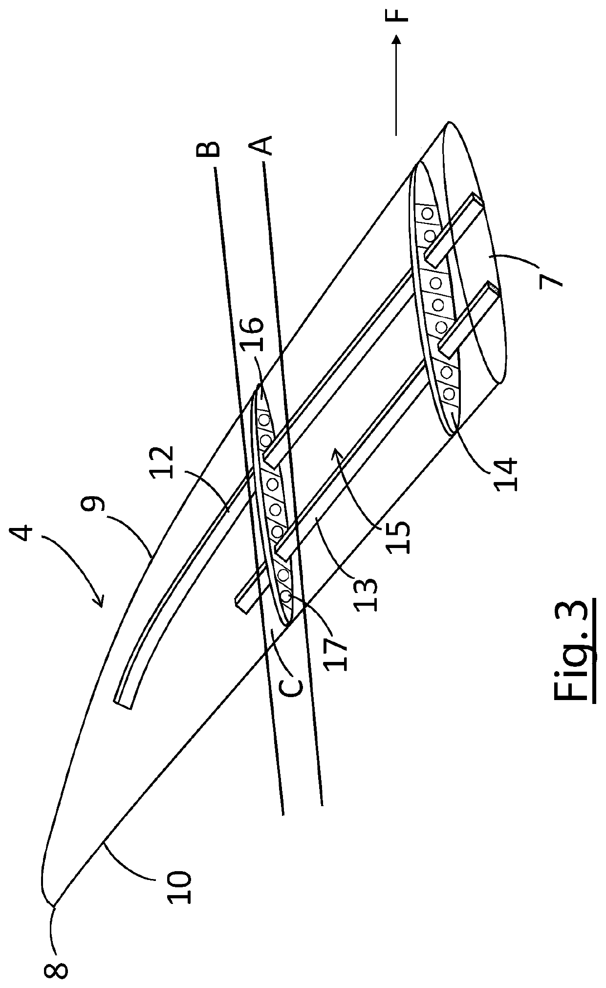
The patent text describes a rib that can be added to a wing tip device to increase its stiffness and provide structural reinforcement against pressure forces, particularly in the transonic region where there are often shock waves. The addition of this rib can make the wing tip device stronger and lighter, and can improve its performance and efficiency in flight. The position and orientation of the rib can be tailored to increase stiffness in different directions, such as the depth of the wing tip device, the direction perpendicular to the mean camber line, and the direction of twisting about the span-wise direction in which the wing tip device extends.

Problems solved by technology

Wing tip devices are relatively complex structures to design and build as they are subject to differing flows at different positions along the wing tip device.
This can present a number of design obstacles.

Method used


Image

  • Rib arrangement in a wing tip device
  • Rib arrangement in a wing tip device
  • Rib arrangement in a wing tip device

Examples


Embodiment Construction

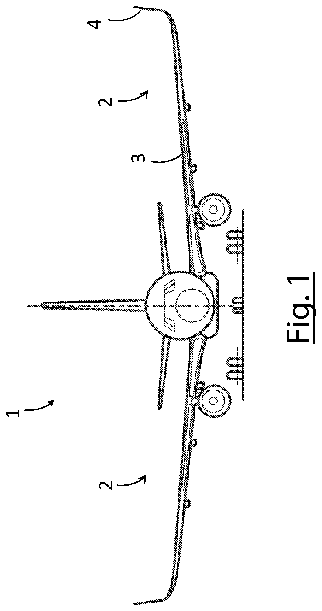
[0073]FIG. 1 illustrates an aircraft 1 according to an embodiment of the invention. The aircraft 1 is a commercial jet aircraft that comprises a pair of wing assemblies 2. The aircraft 1 is a passenger aircraft comprising a passenger cabin comprising a plurality of rows and columns of seat units for accommodating a multiplicity of passengers, in this case more than 50 passengers. The aircraft 1 is a powered aircraft and comprises a pair of engines, mounted under the wing assemblies 2, for propelling the aircraft 1.

[0074]Each wing assembly 2 comprises a wing 3 and a wing tip device in the form of a winglet 4 attached to the outboard tip of the wing 3.

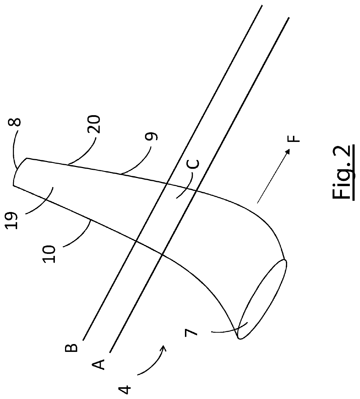
[0075]Referring to FIG. 2, the winglet 4 curves upwardly as it extends outboard in the span wise direction. The curvature of local dihedral increases from a low angle, or an angle of approximately zero, at or near the outboard end of the wing 3 and increases in the outboard direction. The outboard end of the winglet 4 is almost vertical ...


PUM


Abstract

An aircraft (1) having a wing (3) and a wing tip device (4) at the tip of the wing (3), wherein the wing tip device (4) includes a rib (16) positioned in a span wise region (C) of the wing tip device (4) in which transonic flow occurs when the aircraft (1) is in flight. A method of designing an aircraft (1) including predicting where transonic flow occurs on the wing tip device (4) when the aircraft (1) is in flight, and designing the wing tip device (4) with a rib (16) positioned in the span wise region (C) of the wing tip device (4) in which the predicted transonic flow occurs.

Description

RELATED APPLICATION[0001]This application claims priority to United Kingdom (GB) Patent Application 1702588.3 filed Feb. 17, 2017, the entirety of which is incorporated by reference.BACKGROUND OF THE INVENTION[0002]The present invention relates to an aircraft having a wing tip device and to a wing tip device. The present invention also relates to a method of design of an aircraft having a wing tip device and to a method of design of a wing tip device. The present invention also relates to a method of manufacture of an aircraft having a wing tip device and to a method of manufacture of a wing tip device. The present invention further relates to a method of use of an aircraft having a wing tip device.[0003]Wing tip devices are used to improve the efficiency of fixed wing aircraft, predominantly by reducing lift induced drag. Although this may increase the profile drag, the overall lift to drag ratio is increased. This increases fuel efficiency, which is particularly important with pas...

Claims


Application Information

Patent Timeline
Patent Type & Authority Patents(United States)
IPC IPC(8): B64C23/06B64C3/58B64F5/00B64C3/18
CPCB64F5/00B64C23/069B64C3/187Y02T50/10B64C3/58B64C3/28B64C3/36B64C3/185
Inventor HEWSON, RICHARDTULLOCH, WILLIAM
Owner AIRBUS OPERATIONS LTD
Learn More