Crane

a crane and crane technology, applied in the field of cranes, can solve problems such as not preventing erroneous setting, and achieve the effect of quickly determining the suitability of the work information set in the safety apparatus

Active Publication Date: 2020-12-22
TADANO LTD
View PDF5 Cites 0 Cited by
  • Summary
  • Abstract
  • Description
  • Claims
  • Application Information

AI Technical Summary

Benefits of technology

[0012]In a crane of the present invention, the suitability of the work information set in the safety apparatus is quickly determined according to the operation of the crane by the operator. Thus, in the case where a plurality of winches is provided, the operator can recognize that the work information set in the safety apparatus is erroneous.
[0013]In a crane of the present invention, the suitability of an estimated suspension load reflecting a value set by the operator as a requirement, is determined with reference to the actual suspension load. Thus, an operator can recognize errors in work information and the number of turns set in a safety apparatus.
[0014]In a crane of the present invention, an estimated suspension load is calculated considering a friction between a wire rope and a plurality of sheaves or a friction against other movable sections and the efficiency of a hydraulic pressure system. Thus, based on the numeral values corresponding to safety aspects, an operator can recognize errors in work information and the number of turns set in a safety apparatus.
[0015]In a crane of the present invention, the crane can transmit an erroneous setting in the safety apparatus and the contents of the erroneous setting to the operator. Thus, the operator can recognize errors in work information and the number of turns set in a safety apparatus.

Problems solved by technology

Accordingly, the overload prevention apparatus is based on the premise that the setting of the number of turns is equal to the actual number of turns of the hook rope, and does not prevent erroneous setting of the number of turns.

Method used


Image

  • Crane
  • Crane
  • Crane

Examples


Embodiment Construction

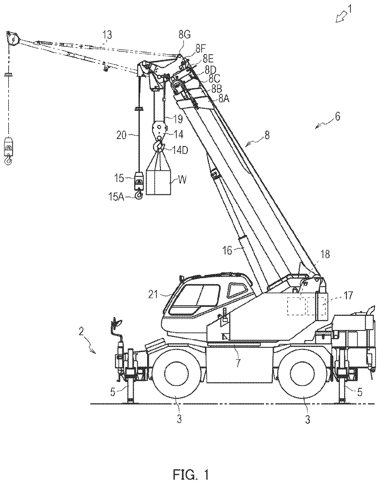
[0030]Crane 1 according to one embodiment of a crane will now be described with reference to FIGS. 1 to 4. Crane 1, which is described as a mobile crane in this embodiment, may be any crane that includes a boom designed to be derricked with a hydraulic cylinder, and a plurality of hydraulic winches.

[0031]As shown in FIG. 1, crane 1 is a mobile crane relocatable to an unspecified location. Crane 1 includes vehicle 2 and crane apparatus 6.

[0032]Vehicle 2 carries crane apparatus 6. Vehicle 2 has a plurality of wheels 3 and travels with engine 4 (see FIG. 6) which serves as a power source. Vehicle 2 is provided with outrigger 5. Outrigger 5 is made up of an overhang beam which can be extended by hydraulic pressure in the width direction of vehicle 2 toward both sides and hydraulic jack cylinders which can be extended in a direction perpendicular to the ground. In the vehicle, outrigger 5 can be extended in the width direction of the vehicle and the workable range of crane 1 can be exten...


PUM


Abstract

Provided is a crane capable of allowing an operator to recognize an error in work information or in a number of windings set in a safety device. A main tension of a main wire rope is calculated from a main output torque of a main winch, a sub output torque of a sub winch, a main drum winding radius of the main winch, and a sub drum winding radius of the sub winch. An estimated hanging load, which is calculated from the main tension, a sub tension of a sub wire rope and the number of windings of the wire rope set in a safety device, is compared with an actual hanging load calculated from fluctuating thrust force and boom information. Thus, the suitability of a work kind or a winding number set in the safety device is determined.

Description

CROSS REFERENCE TO PRIOR APPLICATION[0001]This application is a National Stage Patent Application of PCT International Patent Application No. PCT / JP2017 / 014552 (filed on Apr. 7, 2017) under 35 U.S.C. § 371, which claims priority to Japanese Patent Application No. 2016-078497 (filed on Apr. 8, 2016), which are all hereby incorporated by reference in their entirety.TECHNICAL FIELD[0002]The present invention relates to a crane, particularly to a crane that allows an operator to recognize erroneous settings of the work type of the crane and the number of turns around a sheave in a safety apparatus of the crane.BACKGROUND ART[0003]Conventionally, in cranes, a safety apparatus is provided to prevent falling of the crane and to prevent overloading of the wire rope. In a crane, the performance of the crane itself is changed according to the work content set in the safety apparatus and the number of turns around a sheave. In other words, such falling and overloading of the wire rope are prev...

Claims


Application Information

Patent Timeline
Patent Type & Authority Patents(United States)
IPC IPC(8): B66C15/06B66C15/00B66C23/90B66C23/00
CPCB66C15/00B66C23/905B66C23/90B66C15/065B66C23/54B66C2700/0357B66D1/58
Inventor FUKUMORI, YASUHIROKAWABUCHI, NAOTOYOSHIDA, NAOFUMI
Owner TADANO LTD
Why Eureka
Try Eureka