Aircraft gap seal

a technology for sealing airframes and gaps, applied in the field of seals, can solve the problems of shallow depression in the aerodynamic surface, drag-inducing aerodynamic steps, etc., and achieve the effect of preventing pressure differences across the panel

Active Publication Date: 2020-12-22
AIRBUS OPERATIONS LTD
View PDF13 Cites 3 Cited by
  • Summary
  • Abstract
  • Description
  • Claims
  • Application Information

AI Technical Summary

Benefits of technology

[0012]In such embodiments the material may comprise a substrate and each cell may comprise a uniform pattern of apertures in the substrate. Such an arrangement can have the advantage of providing a relatively ‘closed’ structure in which the seal comprises a higher percentage by volume of substrate than void / aperture. This may help to ensure that the seal is able to withstand the environmental conditions encountered during flight. Such an arrangement may also provide for relatively straightforward manufacture.
[0015]Such embodiments may include a blade seal attached to the first or second external skin panel and extending across the width of the gap to obscure the gap in at least the second configuration. The blade seal thus serves to prevent pressure differences across the panels from causing the gap seal to be dislodged from the gap, e.g. by being ‘blown’ or ‘sucked’ out of the gap. The blade seal is preferably attached to an internal surface of the first or second skin panel.
[0016]The blade seal is preferably configured to slide relative to the other of the first or second external skin panel, respectively, during relative movement of the first and second external skin panels. In this way, relative movement of the panels is not hindered, and the blade seal cannot transmit loads (forces) between the first and second panels.
[0017]In some embodiments the gap seal is fixed (i.e. attached, fastened or otherwise secured) to the opposing edge face of a respective one of the first or second external skin panel, and is not fixed to the opposing edge face of the other of the first or second external skin panel. In this way, relative movement of the panels is not hindered, but the gap seal is retained within the gap. The gap seal may be fixed to the opposing edge face of the first or second external skin panel by bonding.
[0020]The present invention may be applied to folding wing arrangements. In such arrangements the aircraft assembly includes an inner wing section comprising the first external skin panel, and an outer wing section comprising the second external skin panel, the outer wing being pivotable relative to the inner wing between a folded configuration in which the first and second external skin panels are separated, and a flight configuration in which the gap seal is compressed in the first direction. Thus, the gap between panels at either side of the inner-outer wing joint can be easily, accurately and completely filled when the wing is unfolded to its flight configuration, without any additional process step. Moreover, undesirable aerodynamic steps are also avoided.

Problems solved by technology

Known gap seals, such as those discussed above, suffer from the disadvantage that when they are highly compressed they may protrude out of the gap to form a drag-inducing aerodynamic step.
Elastomeric seal members, such as rubber gasket-type seals having an O- or D-shaped cross-section, or lip-type seals, in particular provide a compromised solution because their shape means that they are unable to completely fill the gap without such unwanted protrusion.
Cured sealant beads also suffer from the defect that compression across the gap leads to protrusion out of the gap, and also have the disadvantage that they typically do not completely eliminate the gap in their uncompressed state, but instead provide a shallow depression in the aerodynamic surface.

Method used


Image

  • Aircraft gap seal
  • Aircraft gap seal
  • Aircraft gap seal

Examples


Embodiment Construction

)

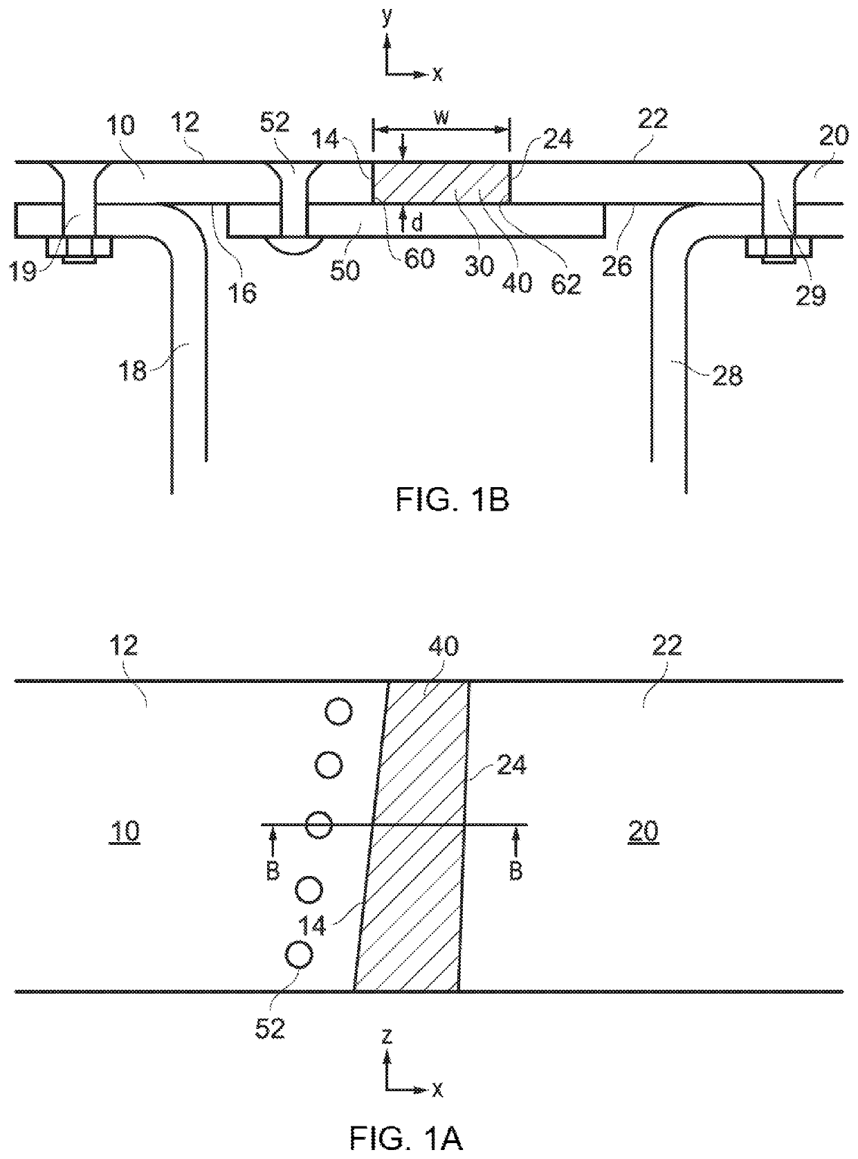
[0029]FIGS. 1A and 1B show plan and section views, respectively, of an aircraft panel assembly according to an embodiment of the invention. First 10 and second 20 panels are arranged adjacent one another so that their outer surfaces 12, 22 together form an aerodynamic surface of the aircraft. The first 10 and second 20 panels are supported by respective structural members 18, 28 to which they are attached by a respective row of fasteners 19, 29.

[0030]In this embodiment loads (forces) are not transferred directly between the first 10 and second 20 panels, though such loads may instead be transmitted via a structural connection (not shown; e.g. a buttstrap). The first 10 and second 20 panels may each comprise a fixed or movable panel, i.e. a panel that is configured to be either fixed or movable during operation of the aircraft. For example, the panels may both be fixed during flight of the aircraft, or one or both of the panels may be movable during flight of the aircraft. The panel...


PUM


Abstract

An aircraft assembly including: first and second external skin panels having opposing edge faces separated by a gap, the gap having a width in a first direction extending between the opposing edge faces and a depth in a second direction generally orthogonal to the first direction; and a gap seal arranged in the gap to at least partially fill the gap, wherein the gap seal is formed of a material configured such that compression of the gap seal in the first direction results in substantially no expansion of the gap seal in the second direction.

Description

RELATED APPLICATION[0001]This application claims priority to GB 1619292.4 filed 15 Nov. 2016, the entire contents of which application is incorporated by reference.FIELD OF THE INVENTION[0002]The present invention relates to a seal for sealing a gap between panels in an aircraft assembly.BACKGROUND OF THE INVENTION[0003]Unfilled gaps between adjacent panels on the aerodynamic surface of an aircraft are undesirable because they generate a drag penalty. Gaps between panels which may move relative to one another are typically filled with an elastomeric seal member which can be compressed as the gap closes. Gaps between fixed panels (i.e. panels which are not intended to be moved during operation of the aircraft) are typically filled with a curable sealant such as a polysulphide sealant.SUMMARY OF THE INVENTION[0004]At its most general the present invention provides an aircraft gap seal formed from a material that, when compressed in the gap width direction, does not expand in the gap d...

Claims


Application Information

Patent Timeline
Patent Type & Authority Patents(United States)
IPC IPC(8): F16J15/447B64C1/12B64C3/26B64C9/00F16J15/10
CPCB64C3/26B64C1/12F16J15/104F16J15/447B64C9/00B64C1/0009B64C3/36B64C7/00B64C9/02F16J15/00
Inventor LAVERNE, JULIENJAGGARD, PHILIPHARDING, MATT
Owner AIRBUS OPERATIONS LTD
Why Eureka
Try Eureka