

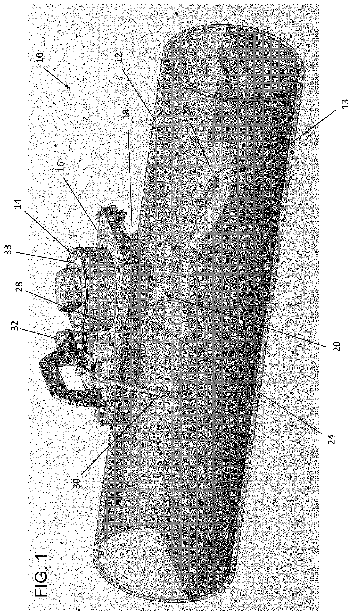
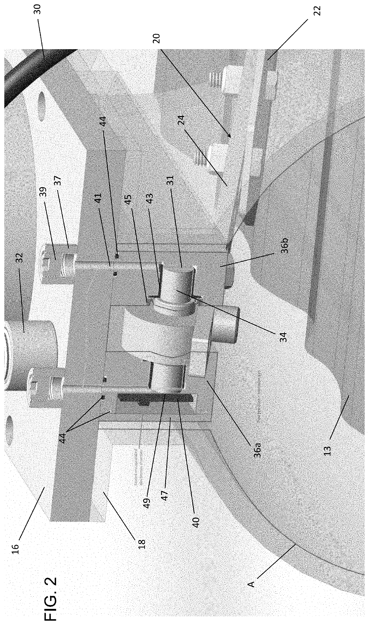
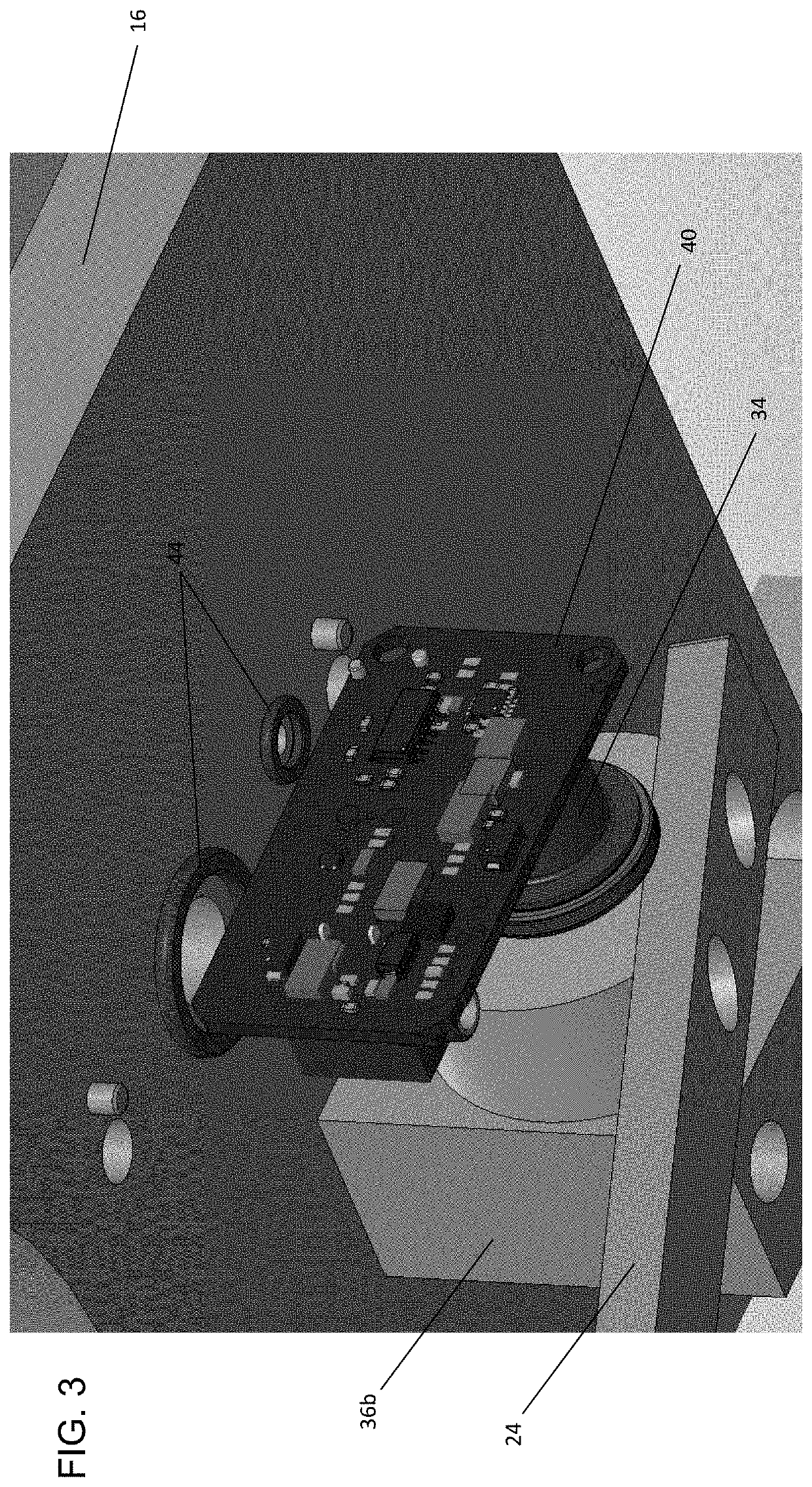
System and device for measuring fluid flow within a conduit
a technology of fluid flow and conduit, applied in the direction of liquid/fluent solid measurement, volume/mass flow by dynamic fluid flow effect, measurement apparatus housing, etc., can solve the problem of reducing the effectiveness of the flow paddle, and achieve the effect of reducing the need for dynamic seals, improving measurement accuracy, and little or no friction in the pivo
- Summary
- Abstract
- Description
- Claims
- Application Information
AI Technical Summary
Benefits of technology
Problems solved by technology
Method used
Image

Examples
Embodiment Construction
[0036]The present disclosure seeks to provide improved systems, devices and methods for measuring fluid flow within a conduit. While various embodiments of the disclosure are described below, the disclosure is not limited to these embodiments, and variations of these embodiments may well fall within the scope of the disclosure which is to be limited only by the appended claims.
[0037]The word “a” or “an” when used in conjunction with the term “comprising” or “including” in the claims and / or the specification may mean “one”, but it is also consistent with the meaning of “one or more”, “at least one”, and “one or more than one” unless the content clearly dictates otherwise. Similarly, the word “another” may mean at least a second or more unless the content clearly dictates otherwise.
[0038]The terms “coupled”, “coupling” or “connected” as used herein can have several different meanings depending on the context in which these terms are used. For example, the terms coupled, coupling, or c...
PUM
 Abstract
Description
Claims
Application Information