In the case in which the determination of the actual volume of the excavation is wrong and the planned number of
truck mixers is insufficient to completely fill the excavation, further unplanned
truck mixers would have to be recalled.
In the case in which the determination of the actual volume of the excavation is wrong and the planned number of
truck mixers is greater than what is really necessary, there would be an increase in the costs due both to hiring unnecessary truck mixers, and to the waste of excess
cement.
During the excavation step, or during the rising step of the excavation device, it is possible that localised collapsing of the walls of the excavation site occur, also called “
cave-ins”, which can generate criticalities in the
casting step.
Indeed,
cave-ins, which can also be of remarkable size, result in an increase in the size of the actual section of the excavation made in the collapsing area with respect to the design section.
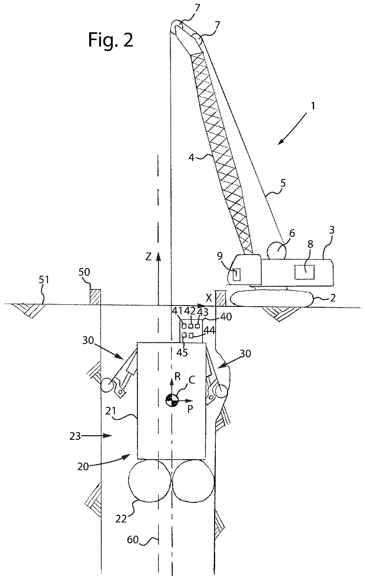
The deviations of the actual profile of the walls and of the actual axis of the excavation can be caused both by unintentional rotations and / or translations of the excavation device during the excavation step, which make the actual axis of the excavation deviate from the theoretical design axis, and by collapsing or
cave-in of the walls of the excavation, which make the actual profile of the wall of the excavation deviate from the theoretical profile.
The lack of containment of the deviations of the actual profile of the walls and of the actual axis of the excavation within the values of the limit design deviations results in a reduction in structural strength and in impermeability of the panel.
This can lead to catastrophic outcomes like in the case of diaphragm walls made in dams.
Currently, the measurements of the actual profile of an excavation just carried out have remarkable difficulties, as well as being burdensome in terms of time and costs.
The fact that such a solution is cloudy hampers the use of optical measuring tools (lasers, lidars,
infrared, encoders, photosensitive sensors, television cameras, photographic cameras), whereas the fact that it has non-uniform density hampers the use of measuring tools with acoustic sensors (
ultrasound,
sonar) or wave sensors (radio,
microwave,
radar), or electro-magnetic sensors.
The measurement with this tool can only be carried out after having carried out a sufficient cleaning of the stabilising
fluid solution, said cleaning resulting in a great worsening of costs and time taken.
In the most extreme cases it may be that the actual profile of the surfaces that constitute the walls of the excavation is so irregular as to be even incompatible with a vertical descent of the sensor, which will end up resting on one of the walls of the excavation.
In addition to the serious problems of costs and time necessary for such an operation, it is also impossible to avoid with any certainty that the residual cloudiness of the solution, or the presence of excavation debris gone into suspension after the re-introduction of the solution itself, alter the measurement.
The very great excavation depths make measurement even more difficult since the tool, being hung on a very
long segment of free cable, tends to oscillate more easily and it takes longer to stop the oscillations spontaneously.
Furthermore, the depth of the excavation hampers the mixing of the clean stabilising
fluid solution, which is introduced in the upper part of the excavation, with the cloudier solution present in the lower part.
Using such a measuring
system it is also necessary to extract the excavation device before carrying out the measurement, with consequent losses of time and productivity.
In the opposite case, indeed, it would be impossible to carry out the measurement in the last segment of the excavation, since the latter is still occupied by the excavation device, and it would be extremely difficult to lower the measuring tool along the theoretical design axis, since such descent would be hampered by the presence of the electro-hydraulic feeding tubes of the excavation device and by the presence of the suspension element of the excavation device itself.
In this case, such a translation at constant depth of the excavation device could not be measured by the inclinometers since such sensors can only detect variations in inclination due to rotations of the excavation device.
Consequently, since such mechanical correction systems do not measure the translations, it is not possible to correctly measure either the position of the excavation device with respect to the theoretical design axis, or the progress of the actual axis of the excavation.
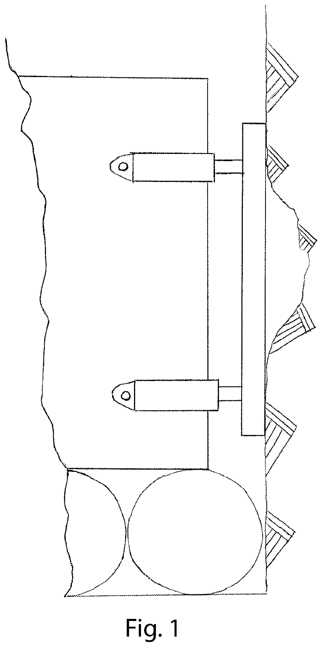
These forces, in some cases, could be such as to deform the walls of the excavation in the contact areas with the flaps, resulting in possible problems concerning the precision of the excavation being made.
Moreover, such mechanical systems cannot measure the deviations of the actual profile of the walls of the excavation, since they cannot establish whether the translations at constant depth of the excavation device, in a direction perpendicular to the theoretical design axis, are due to translation movements of the excavation device, or to deviations of the actual profile of the walls of the excavation.
In fact, if there is a cave-in of the wall of the excavation and the excavation device is resting on such a cave-in, thus carrying out a
horizontal translation at constant depth, the inclinometers could not measure such a translation of the excavation device, since such sensors can only detect variations in inclination due to rotations of the excavation device.
The translation movements of the excavation device during the rising step of the excavation device are accentuated by the presence of clearances between the device and the walls of the excavation, due to the upsetting of the walls carried out by the excavation device itself during subsequent excavation steps.
Such systems do not, however, allow to obtain a measurement of the actual profile of the walls di excavation.
Hence, they are not able to measure cave-ins or any irregularity of the actual profile of the walls such as to vary the actual area or the actual shape of the excavation with respect to the design section.
Moreover, such measuring systems have numerous drawbacks due, for example, to the presence of vibrations of the cables and to the need for constant cleaning of such cables, said drawbacks making the measurements through optical sensors difficult.
Moreover, the wearing of the cables can reduce the precision of measurement.
A further drawback is due to the fact that whenever it is necessary to move the excavation
machine to position it on the point at which a new excavation is made, the measuring
system must be moved or oriented again.


