Swirler for mixing fuel with air in a combustion engine

a technology of swirler and combustion engine, which is applied in the direction of continuous combustion chamber, combustion process, lighting and heating apparatus, etc., can solve the problems of high turbulence in the region, and achieve the effect of improving the mixing result and increasing the turbulen

Active Publication Date: 2020-12-29
SIEMENS ENERGY GLOBAL GMBH & CO KG
View PDF21 Cites 0 Cited by
  • Summary
  • Abstract
  • Description
  • Claims
  • Application Information

AI Technical Summary

Benefits of technology

[0005]It is an objective of the present invention to provide an advantageous swirler with improved mixing properties.
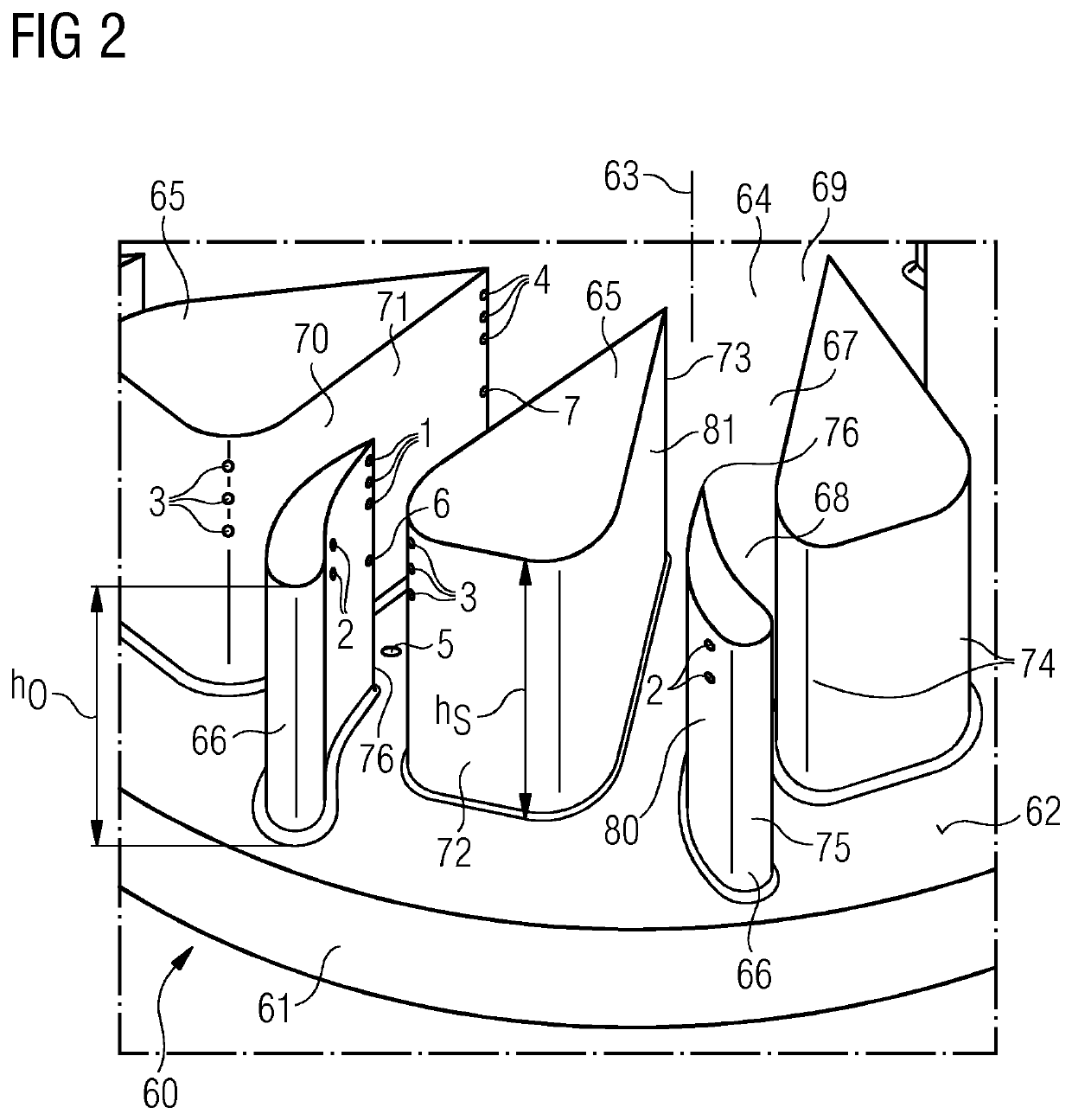
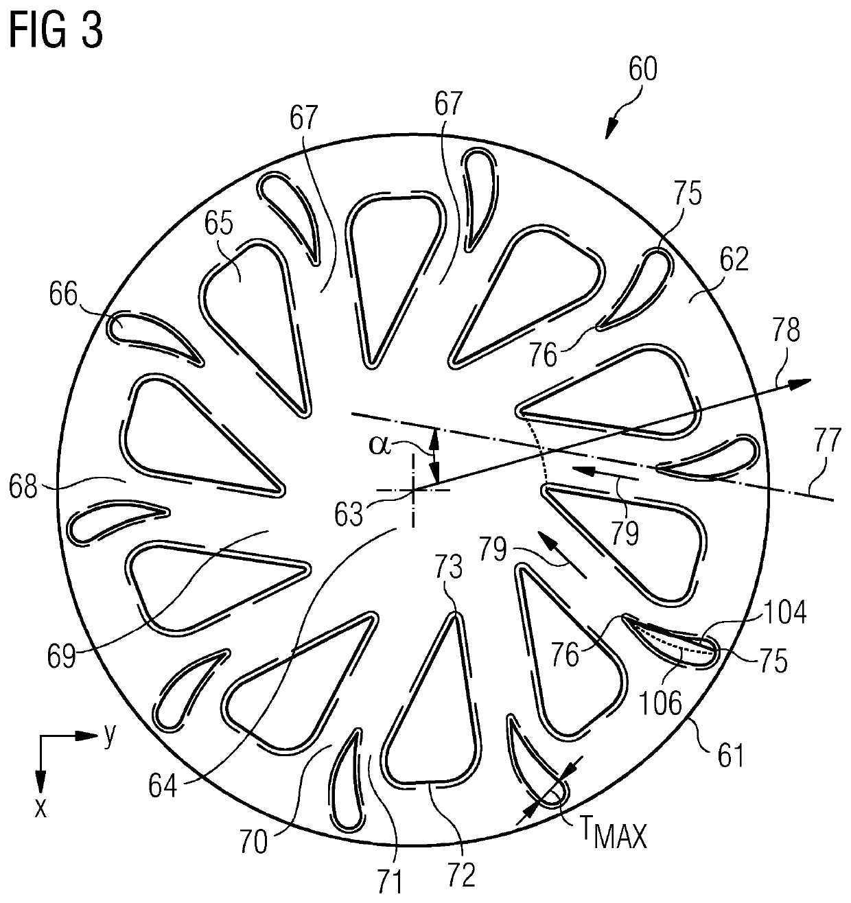
[0012]In advantageous variants least one obstruction element has a round or oval or teardrop shaped or square shaped or diamond shaped cross section in a plane perpendicular to the central axis, which means in a radial plane. The obstructions in the swirler slot should induce turbulence in the flow to improve the mixing of the fuel. The different shapes may be selected with the aim to improve the aerodynamic characteristics, especially the characteristics of the induced turbulence, and / or with the aim to reduce manufacturing costs.
[0016]At least one slot comprises a slot length from the slot inlet to the slot outlet. Advantageously at least one obstruction element, advantageously each obstruction element, penetrates into the slot by a length of less than 70% of the slot length, for example between 10% and 30%, advantageously 20%. A centrally positioned obstruction element at the slot inlet should not penetrate more than 70% of the slot length, but the major benefit would be thought to occur if the penetration was 20% of the swirler slot length from the outside inwards. The balance is between having enough length that the airflow has resolved in that direction and making the joint between the flows sharp. Moreover, the longer the length after the fuel injection the more mixing that can occur within the swirler slot. The length of the obstruction element should also be long enough to prevent the fuel / air mixture flowing back along any of the passages and burning outside a combustion chamber.
[0026]The pilot or a secondary main fuel injector or feed can be positioned at different heights on the trailing edges of the main swirler element or component to further enhance the mixing properties (see position 4 in FIG. 2). Pilot fuel may be injected towards the base of this edge and main fuel may be injected towards the top. A liquid injector can also be placed in one of these locations (see position 7 in FIG. 2). A good liquid pilot location can be facing 90° to the base, from the base of the slot in line with the end of the swirler point (see position 5 in FIG. 2). An injection angled centrally or from the end of the swirler nose radially inwards is also beneficial.
[0031]Generally the invention has the advantage that the additional obstruction elements in the swirler slot induce turbulence and aid mixing, especially mixing with different shapes to increase turbulent mixing at the fuel injection point. Furthermore, novel fuel injection locations are provided, which improve the mixing result.

Problems solved by technology

Where these flows meet there will be a region of high turbulence.

Method used


Image

  • Swirler for mixing fuel with air in a combustion engine
  • Swirler for mixing fuel with air in a combustion engine
  • Swirler for mixing fuel with air in a combustion engine

Examples


Embodiment Construction

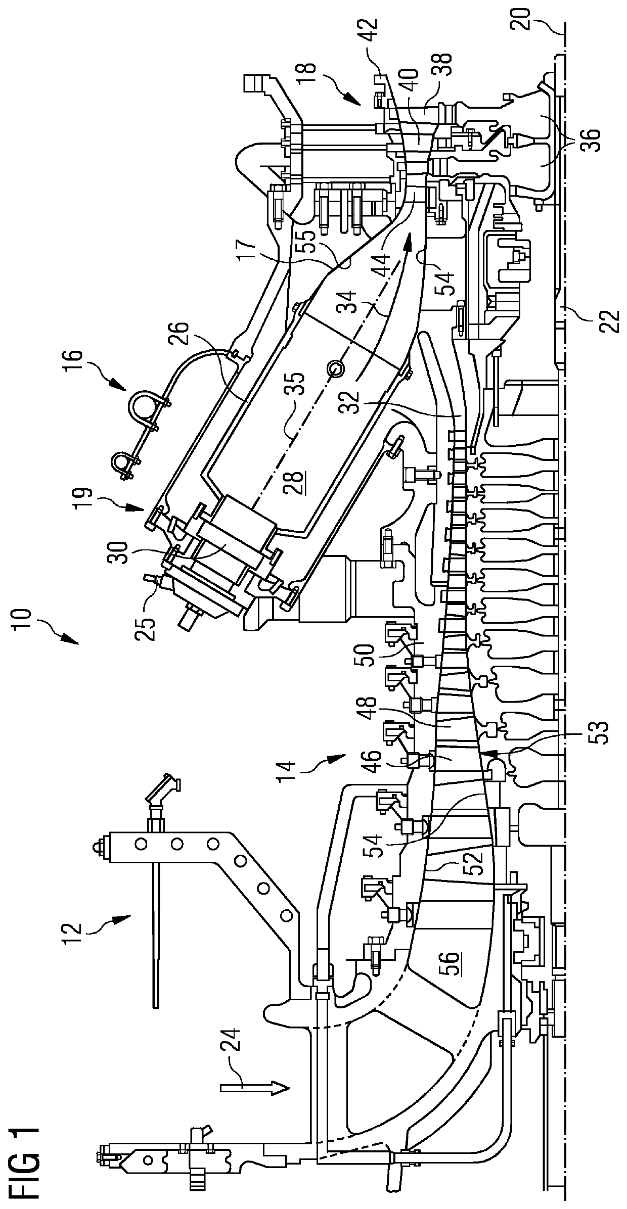
[0044]FIG. 1 shows an example of a gas turbine engine 10 in a sectional view. The gas turbine engine 10 comprises, in flow series, an inlet 12, a compressor section 14, a combustor section 16 and a turbine section 18 which are generally arranged in flow series and generally about and in the direction of a longitudinal or rotational axis 20. The gas turbine engine 10 further comprises a shaft 22 which is rotatable about the rotational axis 20 and which extends longitudinally through the gas turbine engine 10. The shaft 22 drivingly connects the turbine section 18 to the compressor section 14.

[0045]In operation of the gas turbine engine 10, air 24, which is taken in through the air inlet 12 is compressed by the compressor section 14 and delivered to the combustion section or burner section 16. The burner section 16 comprises a burner plenum 26, one or more combustion chambers 28 and at least one burner 30 fixed to each combustion chamber 28. The combustion chambers 28 and the burners ...


PUM


Abstract

A swirler for mixing fuel with air in a combustion engine includes a central axis, a swirler base with an upper surface, a central portion, a number of main swirler elements and a number of obstruction elements. The main swirler elements and the obstruction elements are located at the upper surface of the swirler base and are arranged around the central portion. The main swirler elements form a number of swirler slots configured for directing a fluid towards the central portion. Each swirler slot has a slot inlet and a slot outlet, wherein the slot outlet is located at a smaller radial distance from the central axis than the swirler inlet. Each obstruction element is located at a slot inlet and configured for forming a plurality of flow channels into the swirler slot.

Description

CROSS REFERENCE TO RELATED APPLICATIONS[0001]This application is the US National Stage of International Application No. PCT / EP2017 / 059565 filed Apr. 21, 2017, and claims the benefit thereof. The International Application claims the benefit of European Application No. EP16166716 filed Apr. 22, 2016. All of the applications are incorporated by reference herein in their entirety.FIELD OF THE INVENTION[0002]The present invention relates to a swirler for mixing fuel with air in a combustion engine and a method for mixing fuel with air. The invention further relates to a burner and a gas turbine.BACKGROUND OF INVENTION[0003]Fuel placement and mixing is critical for all combustion systems. The correct fuel placement and the correct mixing profile alters factors such as NOx, burner wall temperatures, combustion efficiency and the position and stability of the flame. Radial swirler combustion systems require placement of the fuel into at least two regions; one for the pilot flame and one for...

Claims


Application Information

Patent Timeline
Patent Type & Authority Patents(United States)
IPC IPC(8): F23R3/14F23R3/28F23C7/00
CPCF23R3/14F23R3/286F23C7/004F23C2900/07001F23R3/28
Inventor DOLMANSLEY, TIMOTHYHIRD, JAMES
Owner SIEMENS ENERGY GLOBAL GMBH & CO KG
Why Eureka
Try Eureka