Use of infrared transparent airframe materials for passive cooling of internal components

a technology of infrared and transparent airframes, applied in the directions of machines/engines, mechanical equipment, transportation and packaging, etc., can solve the problems of restricting flight capabilities based on material limitations, and achieve the effects of reducing mass, reducing speed persistence, and increasing peak mach capability

Active Publication Date: 2021-01-19
RAYTHEON CO
View PDF10 Cites 0 Cited by
  • Summary
  • Abstract
  • Description
  • Claims
  • Application Information

AI Technical Summary

Benefits of technology

[0005]A portion of the engine may be an isolator or a combustor, within a scramjet engine including an inlet, the isolator in which a shock train is contained, the combustor, and a nozzle. The engine is one of a plurality of engines within the propulsion-airframe integrated scramjet aircraft, with a portion of the airframe between the heat-generating portions of each engine and the ambient environment comprising nanocomposite optical ceramic material. The passive reduction of internal engine component temperature in supersonic and hypersonic vehicles resulting from use of nanocomposite optical ceramic materials between the heat-generating portions of each engine and the ambient environment, and resulting heat dissipation from the engine components directly to the ambient environment, can increase peak Mach capability and / or reduce mass, while also cooling of internal electronics for lower speed persistence applications.

Problems solved by technology

For hypersonic vehicles, high speed air flow, electronic components and combustion cause high levels of heating and high temperatures on various components including engine components, ultimately restricting flight capabilities based on material limitations driven by temperature.

Method used


Image

  • Use of infrared transparent airframe materials for passive cooling of internal components
  • Use of infrared transparent airframe materials for passive cooling of internal components
  • Use of infrared transparent airframe materials for passive cooling of internal components

Examples


Embodiment Construction

[0013]It should be understood at the outset that, although exemplary embodiments are illustrated in the figures and described below, the principles of the present disclosure may be implemented using any number of techniques, whether currently known or not. The present disclosure should in no way be limited to the exemplary implementations and techniques illustrated in the drawings and described below. Additionally, unless otherwise specifically noted, articles depicted in the drawings are not necessarily drawn to scale.

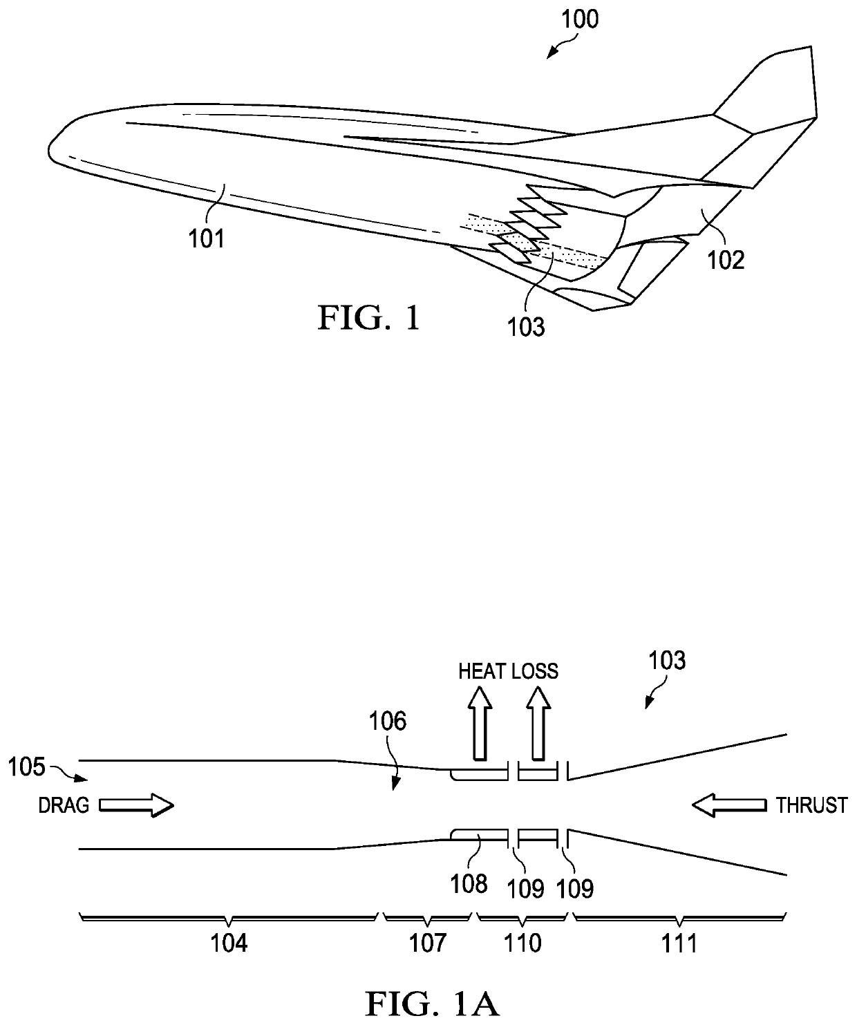
[0014]Aircraft flight capability is restricted by material limitations and, for hypersonic vehicles, is at least partially driven by temperature. Flight speeds are limited to reduce aerodynamic heating of the engine flow path, but this reduces performance of the system. Reducing temperatures on hardware increases capability. Engine components are cooled using liquid fuel that passes through cooling channels, providing benefits from preheating the fuel before combustio...


PUM


Abstract

Passive reduction of internal jet engine component temperature in supersonic and hypersonic vehicles results from use of nanocomposite optical ceramic materials between the heat-generating portions of each jet engine and the ambient environment, allowing heat dissipation from the jet engine components directly to the ambient environment. A propulsion-airframe integrated scramjet aircraft includes a jet engine and an airframe supporting the jet engine, with at least a portion of the airframe between a heat-generating portion of the jet engine and an ambient environment comprising a nanocomposite optical ceramic material in the form of a panel or a grid of windows each supported within a frame. The nanocomposite optical ceramic material portion of the airframe disposed between the heat-generating portion of the jet engine and the ambient environment is infrared-transparent, and may transmit at least 75% of heat energy from the heat-generating portion of the jet engine to the ambient environment.

Description

TECHNICAL FIELD[0001]The present disclosure is directed in general to cooling of high temperature engine components in hypersonic and other vehicles and more particularly to infrared transparent materials adjacent heat generating components in such hypersonic and other vehicles.BACKGROUND OF THE DISCLOSURE[0002]For hypersonic vehicles, high speed air flow, electronic components and combustion cause high levels of heating and high temperatures on various components including engine components, ultimately restricting flight capabilities based on material limitations driven by temperature.SUMMARY OF THE DISCLOSURE[0003]A propulsion-airframe integrated aircraft includes a heat-generating engine and an airframe supporting the engine, with at least a portion of the airframe between a heat-generating portion of the engine and an ambient environment comprising a nanocomposite optical ceramic material. The nanocomposite optical ceramic material portion of the airframe disposed between the he...

Claims


Application Information

Patent Timeline
Patent Type & Authority Patents(United States)
IPC IPC(8): F01P3/00B64D33/08B64D27/16F02K7/10F02K1/82F02K7/14
CPCB64D33/08B64D27/16F02K1/825F02K7/10F02K7/14F05D2220/10F05D2260/221F05D2300/603B64C30/00B64D33/10Y02T50/60
Inventor WOOD, ADAM
Owner RAYTHEON CO
Why Eureka
Try Eureka