
Method for generating an electro spun fiber medical implant

a technology of electro-spinning fiber and medical implants, which is applied in the direction of additive manufacturing processes, blood vessels, prostheses, etc., can solve the problems of increasing susceptibility to infection, lack of growth potential, and 70% mortality rate in the first year of life, so as to improve patient care, promote neo-tissue formation, and reduce complications

Active Publication Date: 2021-01-19
RES INST AT NATIONWIDE CHILDRENS HOSPITAL +2
View PDF10 Cites 0 Cited by
  • Summary
  • Abstract
  • Description
  • Claims
  • Application Information

AI Technical Summary

Benefits of technology

The patent text describes a technique for creating patient-specific electro spun fiber vascular grafts using 3D images obtained from patients with congenital heart disease. These grafts promote neo-tissue formation and reduce complications, which improves patient care. The grafts can be used in various applications such as heart surgery and vascular disease treatment. The technique drastically enhances the available treatments for children and adults with CHD and vascular disease.

Problems solved by technology

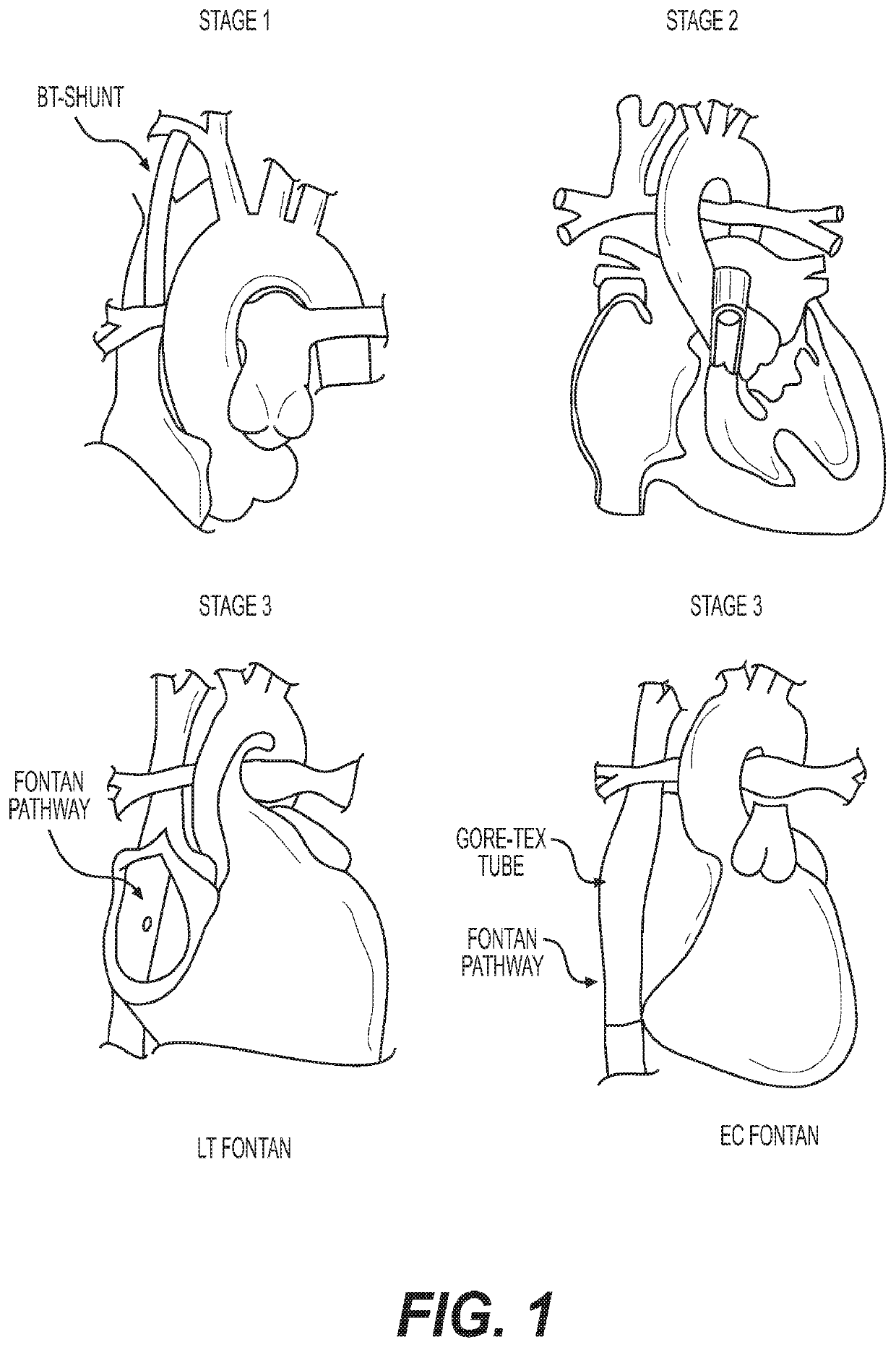
In untreated SVAs, only one of two ventricles is of functional size and is associated with a 70% mortality rate during the first year of life.
However, the implanted grafts include complications such as progressive obstruction, lack of growth potential, increased susceptibility to infection, and increased risk for thromboembolic complications.
Further, biological grafts lack growth potential and have poor durability due to calcification and secondary graft failure (e.g., the grafts have failure rates of 70-100% in 10-15 years), and thus require subsequent replacement.
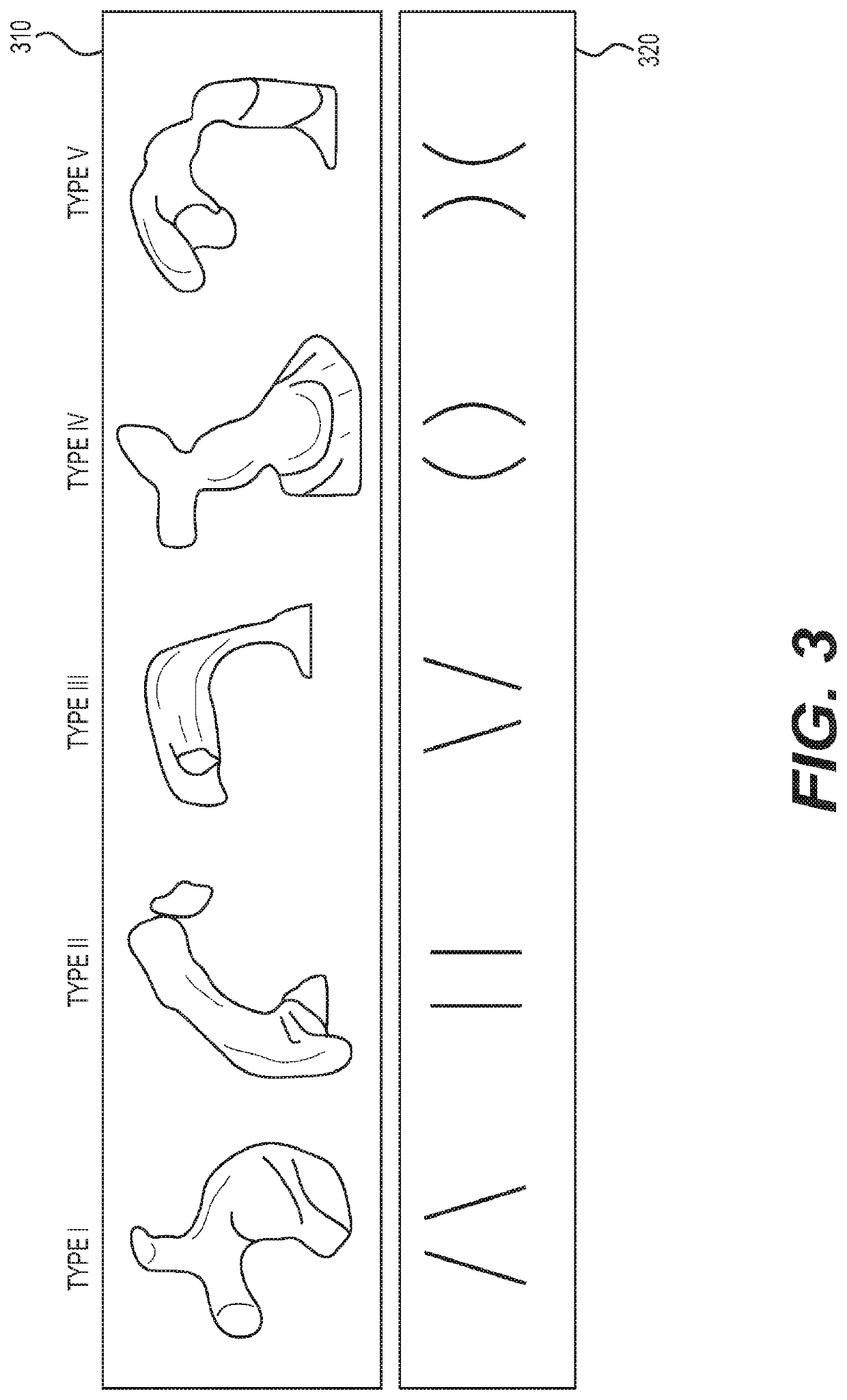
However, current TEVG strategies do not address the issue of having diversity in the graft shape of each patient.
In other words, the current TVEGs do not address the diverse anatomic requirements of individual patients.
Accordingly, surgeons are faced with the problem of having to construct complex vessel shapes using a limited choice of grafts under crucial time constraints during surgery.

Method used


Image

  • Method for generating an electro spun fiber medical implant
  • Method for generating an electro spun fiber medical implant
  • Method for generating an electro spun fiber medical implant

Examples


Embodiment Construction

[0031]Exemplary embodiments are illustrated in the referenced figures of the drawings. It is intended that the embodiments and figures disclosed herein are to be considered illustrative rather than restrictive. No limitation on the scope of the technology and of the claims that follow is to be imputed to the examples shown in the drawings and discussed herein.

[0032]The embodiments are mainly described in terms of particular processes and systems provided in particular implementations. However, the processes and systems will operate effectively in other implementations. Phrases such as ‘an embodiment’, ‘one embodiment’ and ‘another embodiment’ may refer to the same or different embodiments. The embodiments will be described with respect to methods and compositions having certain components. However, the methods and compositions may include more or less components than those shown, and variations in the arrangement and type of the components may be made without departing from the scop...


PUM

PropertyMeasurementUnit
flow rateaaaaaaaaaa
flow rateaaaaaaaaaa
linear displacement resolutionaaaaaaaaaa

Abstract

A method for generating a electro spun fiber medical implant including determining dimensions of a portion of anatomy of a patient corresponding to the electro spun fiber medical implant via medical imaging, generating a model of the portion of the anatomy based on the dimensions, the model including one or more solid areas and one or more void areas encompassed within the one or more solid areas, inverting the model to generate a mandrel model, the mandrel model generated based on the one or more void areas, generating the mandrel based on the mandrel model, the mandrel including at least one electrically conductive material therein, and applying an electro-spinning process to the mandrel to generate the electro spun fiber medical implant which circumscribes the mandrel, wherein the mandrel is removable from within the electro spun fiber medical implant after a disassembly process.

Description

CROSS-REFERENCE TO RELATED APPLICATIONS[0001]This application is based upon and claims the benefit of priority to provisional U.S. Application No. 62 / 209,990, filed Aug. 26, 2015, the entire contents of which are incorporated herein by reference.BACKGROUNDField of Disclosure[0002]The present disclosure relates generally to a method of manufacturing patient specific tissue-engineered vascular conduits based on electrospinning. In particular, the present disclosure relates to creating vascular grafts for use in the repair of congenital heart defects, and other vascular abnormalities and diseases.Description of Related Art[0003]The background description provided herein is for the purpose of generally presenting the context of the disclosure. Work of the presently named inventors, to the extent the work is described in this background section, as well as aspects of the description that may not otherwise qualify as prior art at the time of filing, are neither expressly nor impliedly adm...

Claims


Application Information

Patent Timeline
Patent Type & Authority Patents(United States)
IPC IPC(8): B29C33/44B29C33/48B29C33/52D01D5/00A61F2/06B29C64/106B29C64/112B29C33/38B33Y50/00B33Y80/00B29C64/386B29L31/00B33Y10/00A61B34/10
CPCD01D5/0076A61F2/06B29C33/3842B29C33/485B29C64/106B29C64/112B29C64/386B33Y50/00B33Y80/00D01D5/003D01D5/0015D01D5/0023D01D5/0038D01D5/0046A61B34/10A61B2034/105A61B2034/108A61F2240/004A61F2240/008B29L2031/757B29L2031/7532B29L2031/7534B33Y10/00D01D5/0007D10B2331/041D10B2509/06
Inventor KRIEGER, AXELHIBINO, NARUTOSHIJOHNSON, JEDOPFERMANN, JUSTINDORGAN, CAROLYN COCHENOURBREUER, CHRISTOPHER K.
Owner RES INST AT NATIONWIDE CHILDRENS HOSPITAL
Learn More