
Targeting saccade landing prediction using visual history

a technology of visual history and target point, applied in the direction of static indicating device, image enhancement, instruments, etc., can solve the problems of wasting valuable graphics processing device resources, limited display of graphical items at a given point, and inability to fully appreciate user-friendly graphical items, etc., to achieve the effect of improving the prediction of the gaze poin

Active Publication Date: 2021-01-19
TOBII TECH AB
View PDF94 Cites 4 Cited by
  • Summary
  • Abstract
  • Description
  • Claims
  • Application Information

AI Technical Summary

Benefits of technology

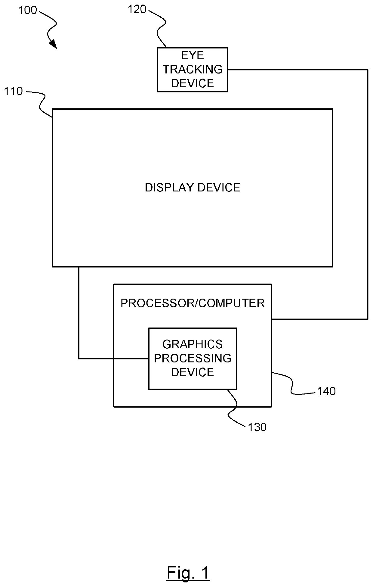
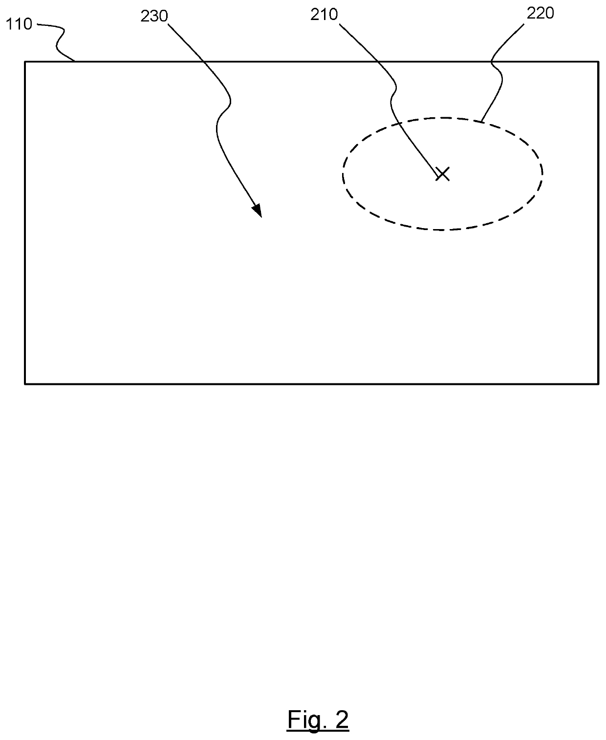
[0007]To illustrate, foveated rendering may be supported by using ballistic prediction to predict where a gaze point will land on a display. By also detecting a change in the content presented on the display using the visual history available from the recorded images, the prediction of the gaze point can be improved by nudging the gaze point to land in an area having a large content change, where this ara may have likely attracted the user's attention.

Problems solved by technology

This is typically limited by the capabilities of the hardware embodying the graphics processing device, including processors, memory, and communication channels.
Additionally, the amount of graphical items able to be displayed on a screen at a given point can be limited by communication limits between the graphics processing device and computer.
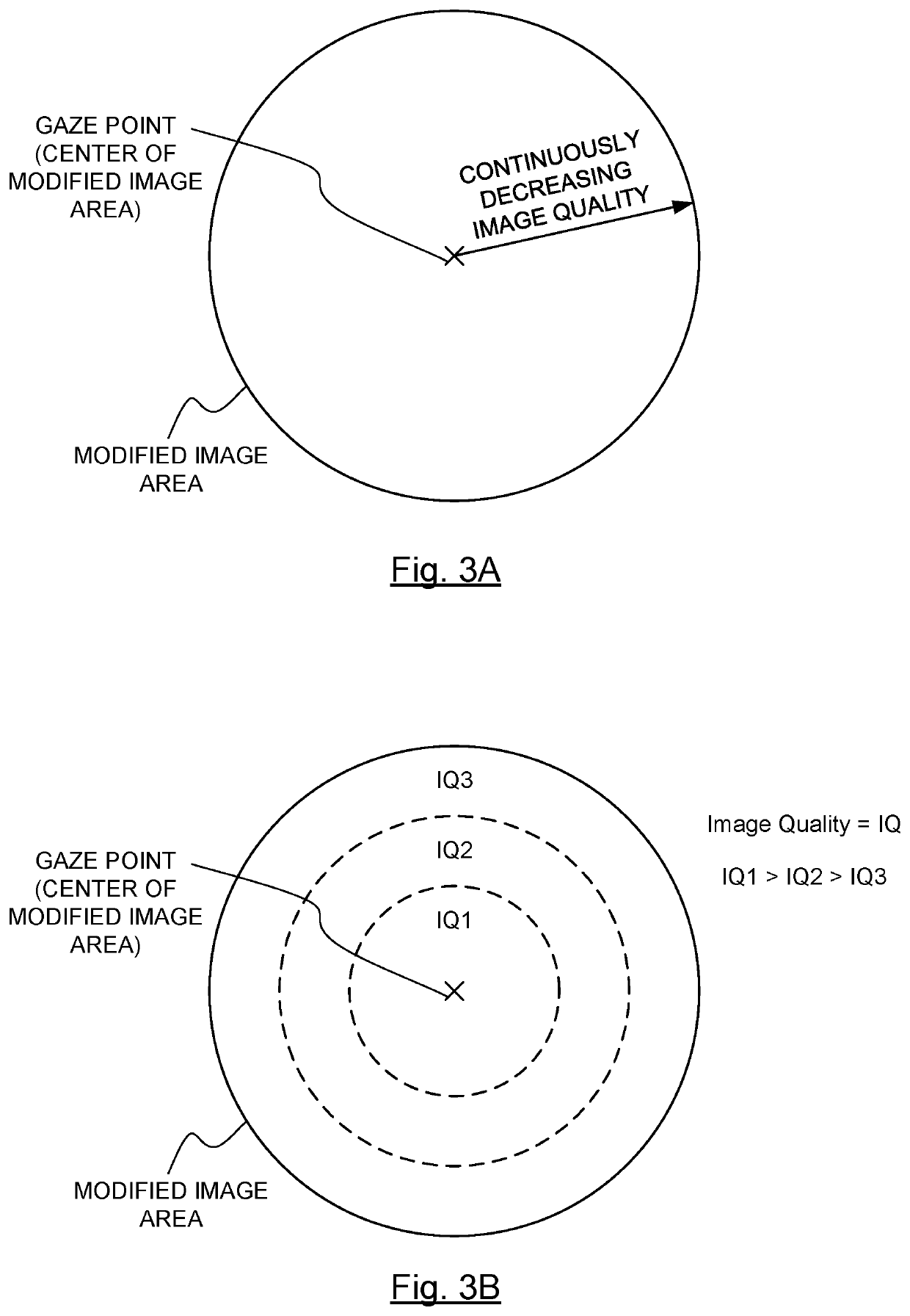
This wastes valuable graphics processing device resources to produce graphical items that cannot be fully appreciated by the user because the visual acuity of a human drops dramatically outside those images immediately focused on.

Method used


Image

  • Targeting saccade landing prediction using visual history
  • Targeting saccade landing prediction using visual history
  • Targeting saccade landing prediction using visual history

Examples


Embodiment Construction

[0026]The ensuing description provides exemplary embodiments only, and is not intended to limit the scope, applicability or configuration of the disclosure. Rather, the ensuing description of the exemplary embodiments will provide those skilled in the art with an enabling description for implementing one or more exemplary embodiments. It being understood that various changes may be made in the function and arrangement of elements without departing from the spirit and scope of the invention as set forth in the appended claims.

[0027]Specific details are given in the following description to provide a thorough understanding of the embodiments. However, it will be understood by one of ordinary skill in the art that the embodiments may be practiced without these specific details. For example, circuits, systems, networks, processes, and other elements in the invention may be shown as components in block diagram form in order not to obscure the embodiments in unnecessary detail. In other i...


PUM


Abstract

According to the invention, techniques for refining a ballistic prediction are described. In an example, an eye tracking system may record images over time of content presented on a display. Saccade data may be received and used as a trigger to retrieve particular ones of the recoded images. The eye tracking system may compare the images to identify a change in the content. The location of this change may correspond to a sub-area of the display. The output of the ballistic prediction may include a landing point that represents an anticipated gaze point. This landing point may be adjusted such that a gaze point is now predicted to fall within the sub-area when the change is significant.

Description

CROSS-REFERENCE TO RELATED APPLICATIONS[0001]This application is a continuation-in-part of U.S. patent application Ser. No. 16 / 132,656, filed Sep. 17, 2018, which is a continuation of U.S. patent application Ser. No. 15 / 476,650, filed Mar. 31, 2017, which is a continuation-in-part of U.S. patent application Ser. No. 15 / 270,783, filed Sep. 20, 2016, which is a continuation-in-part of U.S. patent application Ser. No. 14 / 197,171, filed Mar. 4, 2014, which claims priority to Provisional U.S. Patent Application No. 61 / 772,366, filed Mar. 4, 2013, the entire disclosures of which are hereby incorporated by reference, for all purposes, as if fully set forth herein.BACKGROUND OF THE INVENTION[0002]Graphical items may be used on a display to show data and information to a viewer. These graphical items may include text, images, and video. Graphical items in the area of computing are well known and have been in use for many years. Recently, showing three dimensional (3D) graphical items on a di...

Claims


Application Information

Patent Timeline
Patent Type & Authority Patents(United States)
IPC IPC(8): G06F3/01G06F3/039G09G5/373G09G5/37G06T5/00G06K9/00G06F3/147G06V20/20G06V40/19
CPCG06F3/013G06F3/039G06F3/147G06K9/00G06K9/00604G06K9/00671G06T5/00G09G5/37G09G5/373G06F2203/011G09G2320/0261G09G2320/103G09G2354/00G06V40/19G06V20/20G06F18/00
Inventor NIJS, DAAN
Owner TOBII TECH AB
Learn More