Method and apparatus to control an armature rotating within a magnetic circuit

a technology of magnetic circuit and armature, which is applied in the direction of magnetic circuit rotating parts, dynamo-electric brakes/clutches, and shape/form/construction of magnetic circuits, etc., and can solve problems such as technical solutions

Undetermined Publication Date: 2021-01-19
HANAGAN MICHAEL
View PDF7 Cites 0 Cited by
  • Summary
  • Abstract
  • Description
  • Claims
  • Application Information

AI Technical Summary

Problems solved by technology

This presents a technical problem for which a tec

Method used


Image

  • Method and apparatus to control an armature rotating within a magnetic circuit
  • Method and apparatus to control an armature rotating within a magnetic circuit
  • Method and apparatus to control an armature rotating within a magnetic circuit

Examples


Embodiment Construction

[0028]A Method and Apparatus to Control an Armature Rotating within a Magnetic Circuit is disclosed.

[0029]As used in this specification, armature or similar language refers to a rotating assembly, commonly called a rotor. As used in this specification, a stator or similar language refers to a stationary non-rotating assembly with respect to the armature.

[0030]Depending upon the construction of the armature and stator, either the outside assembly can be stationary with the inner assembly rotating, or if the inner assembly is stationary the outer assembly can rotate.

[0031]While embodiments of the invention may illustrate a particular orientation of a magnetic field, it is to be understood that the orientation is for explanation and not a required orientation. That is, embodiments having the magnetic fields in other orientations are also possible.

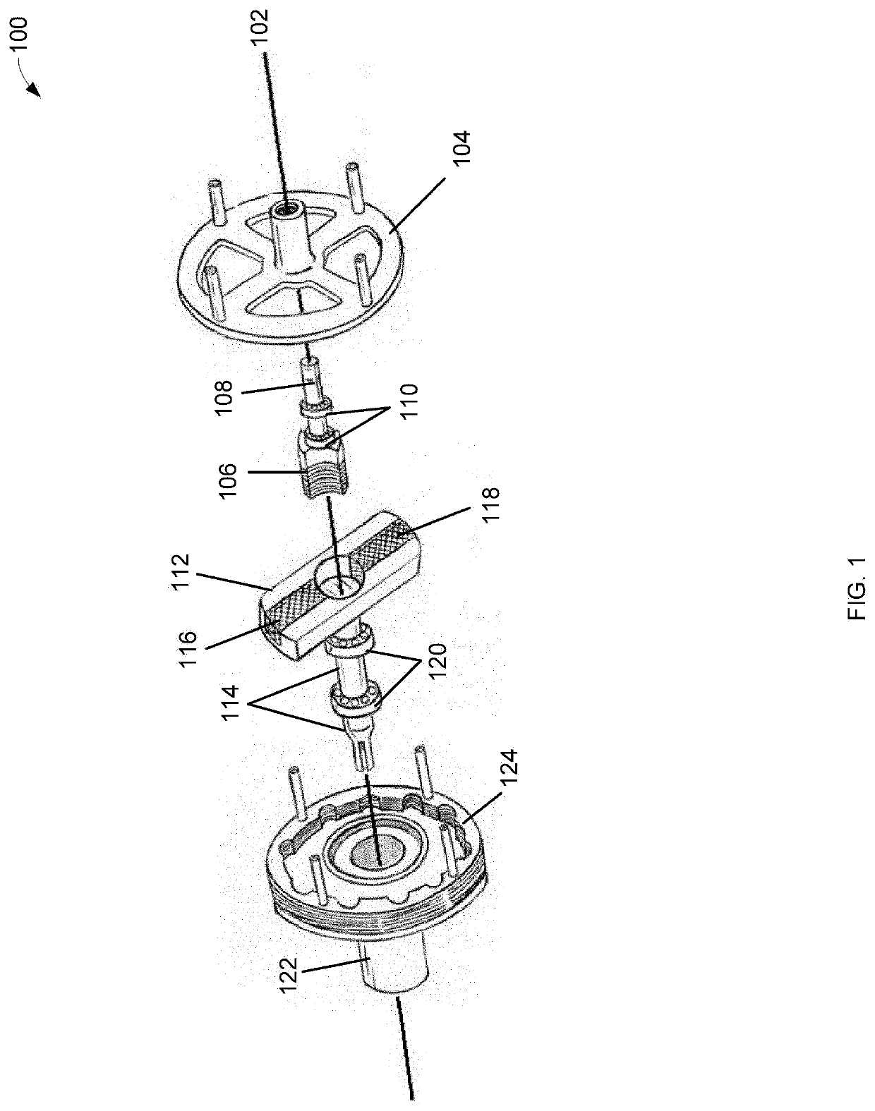
[0032]FIG. 1 illustrates, generally at 100, an exploded view of one embodiment of the invention showing an arrangement of major components al...


PUM


Abstract

A Method and Apparatus to Control an Armature Rotating within a Magnetic Circuit have been disclosed. A rotatable radial field control is positioned between permanent magnets on a rotatable armature that is positioned within a stator. The rotatable radial field control rotation controls the rotation of the armature.

Description

FIELD OF THE INVENTION[0001]The present invention pertains to a magnetic circuit. More particularly, the present invention relates to a Method and Apparatus to Control an Armature Rotating within a Magnetic Circuit.BACKGROUND OF THE INVENTION[0002]Electromagnetics are currently used in a stator and / or armature to control rotation. Electromagnetics requires the use of electricity.[0003]This presents a technical problem for which a technical solution is needed using a technical means.BRIEF DESCRIPTION OF THE DRAWINGS[0004]The invention is illustrated by way of example and not limitation in the figures of the accompanying drawings. Same numbered items are not necessarily alike.[0005]The accompanying Figures illustrate various non-exclusive embodiments of the invention.[0006]FIG. 1 illustrates, generally at 100, an exploded view of one embodiment of the invention showing an arrangement of major components along a longitudinal axis[0007]FIG. 2 illustrates, generally at 200, one embodimen...

Claims


Application Information

Patent Timeline
IPC IPC(8): H02K1/16H02K1/14H02K5/16H02K21/10H02K1/27
CPCH02K1/16H02K1/14H02K1/2706H02K5/16H02K21/10H02K49/102H02K49/10
Inventor HANAGAN, MICHAEL
Owner HANAGAN MICHAEL
Why Eureka
Try Eureka