Axial exciting mixed reluctance motor
A technology of axial excitation and reluctance motor, which is applied in the direction of magnetic circuit shape/style/structure, electrical components, electromechanical devices, etc., and can solve problems such as inability to compensate and control the magnetic potential of permanent magnets, and the limitation of motor torque
- Summary
- Abstract
- Description
- Claims
- Application Information
AI Technical Summary
Problems solved by technology
Method used
Image
Examples
specific Embodiment approach 1
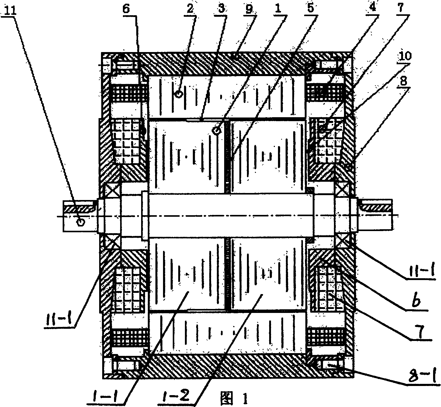
[0005] Specific embodiment one: Referring to Fig. 1, this embodiment consists of a rotor core 1, a stator core 2, a radial field winding 4, a permanent magnet 5, an axial field compensation control winding 7, a magnetic end cover 8, and a magnetic machine The shell 9 and the non-magnetic shaft 11 are composed. The magnetically permeable casing 9 covers the outside of the stator core 2 , the rotor core 1 is arranged inside the stator core 2 , and there is a radial air gap 3 between the rotor core 1 and the stator core 2 . A number of large poles are set on the stator core 2 according to the number of phases of the motor. There are several small teeth on the large poles of each phase iron core. number of phases), radial multi-phase excitation windings 4 are arranged on the pole body. The rotor core 1 is set on the non-magnetic shaft 11, the rotor core 1 is divided into the left rotor core 1-1 and the right rotor core 1-2 at the center of the axis, and the sheet-shaped permanent...
specific Embodiment approach 2
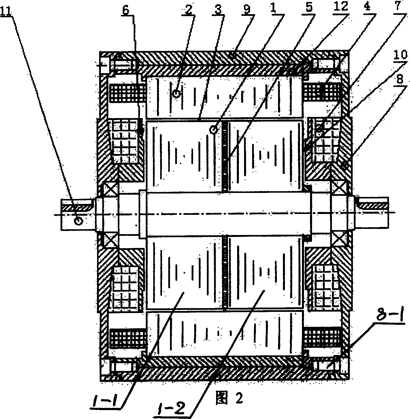
[0006] Specific embodiment 2: Referring to FIG. 2 , the difference between this embodiment and specific embodiment 1 is that a non-magnetic permeable body 12 is provided between the magnetic permeable housing 9 and the stator core 2 . In the magnetic system of the axial excitation hybrid reluctance motor of the present embodiment, the magnetic flux of the permanent magnet 5 passes through the left rotor iron core 1-1, the radial air gap 3, the stator iron core 2, the air gap 3 and the right rotation The sub-iron core 1-2 is closed. The magnetic flux of the axial excitation compensation control winding 7 passes through the axial excitation compensation control winding core 6, the axial air gap 10, the left rotor core 1-1, the radial air gap 3, the stator core 2, the radial air gap Gap 3, right rotor iron core 1-2, axial air gap 10, magnetically permeable end cover 8, magnetically permeable casing 9 and magnetically permeable end cover 8 are closed. The magnetic flux of the rad...
specific Embodiment approach 3
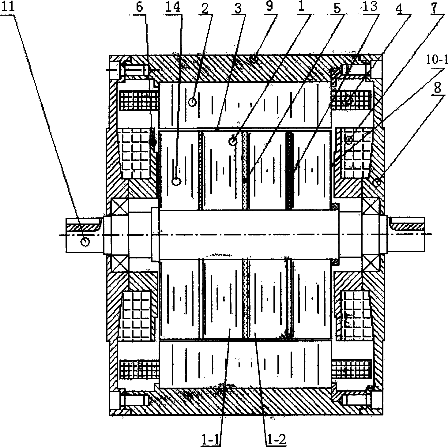
[0007] Specific implementation mode three: see image 3 The difference between this embodiment and the specific embodiment 1 is that an axial magnetic isolation block 13 and an axial iron core 14 are sequentially fixed on the outer sides of the left rotor core 1-1 and the right rotor core 1-2 respectively, There is a gap 10-1 between the axial iron core (14) and the axial excitation compensation control winding iron core 6. In the magnetic system of the axial excitation hybrid reluctance motor, the magnetic flux of the permanent magnet 5 is closed through the rotor core 1-1, the radial air gap 3, the stator core 2, the air gap 3 and the rotor core 1-2. The magnetic flux of the axial excitation compensation control winding 7 passes through the axial excitation compensation control winding core 6, the gap 10-1, the rotor core 14, the radial air gap 3, the stator core 2, the magnetic conduction casing 9 and the magnetic conduction The end cap 8 is closed. The magnetic flux of th...
PUM
 Abstract
Description
Claims
Application Information
 - R&D
- Intellectual Property
- Life Sciences
- Materials
- Tech Scout
- Unparalleled Data Quality
- Higher Quality Content
- 60% Fewer Hallucinations
Browse by: Latest US Patents, China's latest patents, Technical Efficacy Thesaurus, Application Domain, Technology Topic, Popular Technical Reports.
© 2025 PatSnap. All rights reserved.Legal|Privacy policy|Modern Slavery Act Transparency Statement|Sitemap|About US| Contact US: help@patsnap.com


