
A three-degree-of-freedom magnetic levitation switched reluctance motor

A switched reluctance motor and magnetic levitation technology, which is applied in the direction of electrical components, electromechanical devices, electric components, etc., can solve the problems of increasing the axial length of the levitation motor system, reducing the critical speed and power density, and achieving simple structure and interphase coupling Small, the effect of reducing manufacturing costs

Active Publication Date: 2016-08-24
NANJING UNIV OF AERONAUTICS & ASTRONAUTICS
View PDF4 Cites 0 Cited by
  • Summary
  • Abstract
  • Description
  • Claims
  • Application Information

AI Technical Summary

Problems solved by technology

Axial magnetic bearings will inevitably increase the axial length of the levitation motor system, thereby reducing the critical speed and power density

Method used


Image

  • A three-degree-of-freedom magnetic levitation switched reluctance motor
  • A three-degree-of-freedom magnetic levitation switched reluctance motor
  • A three-degree-of-freedom magnetic levitation switched reluctance motor

Examples


Embodiment Construction

[0019] Below in conjunction with accompanying drawing, the present invention is described in further detail:

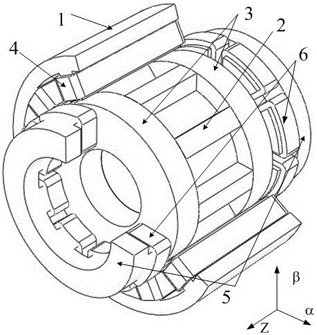
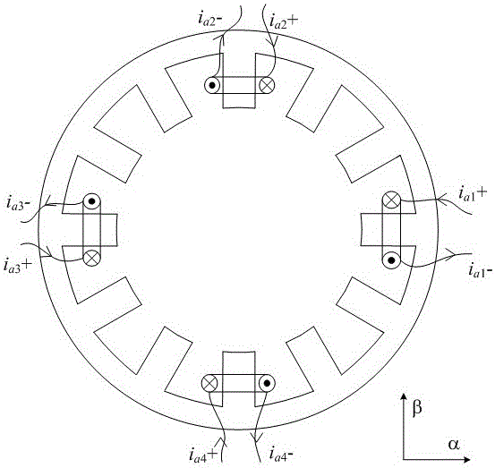
[0020] Such as figure 1 Shown: the three-dimensional structure schematic diagram of the three-phase 12 / 8 pole 3 degrees of freedom magnetic levitation switched reluctance motor of the present invention, including radial field motor stator 1, salient pole rotor 2, cylindrical rotor 3, radial field motor winding 4, magnetic bearing Stator 5 and magnetic bearing winding 6. The radial field motor (that is, bearingless switched reluctance motor) stator and the two axial magnetic bearing stators are salient pole structures, in which the number of teeth of the motor stator is 12, and the number of teeth of the magnetic bearing stator is an even number. The motor stator and the magnetic bearing stator There is a winding on each tooth, and the winding form is a concentrated winding; the rotor is formed by axially laminating a salient pole rotor and two cylindrical rotors, and...


PUM


Abstract

The invention relates to a three-degree-of-freedom magnetic suspension switched reluctance motor, which belongs to the field of magnetic suspension switched reluctance motors and magnetic suspension bearings. The motor stator is composed of a radial magnetic field motor stator and two magnetic bearing stators. Both the radial magnetic field motor stator and the two magnetic bearing stators have a salient pole structure. Each stator tooth of the radial magnetic field motor stator is wound with a motor winding. A magnetic bearing winding is wound on each stator tooth of the magnetic bearing stator; the rotor is composed of a salient pole rotor and two cylindrical rotors axially superimposed, the salient pole rotor is located between the two cylindrical rotors, and the salient pole rotor is used to generate torque , a cylindrical rotor is used to generate radial and axial suspension forces. The invention provides a three-degree-of-freedom magnetic suspension switched reluctance motor, which integrates a bearingless switched reluctance motor and an axial magnetic suspension bearing, and is highly integrated; there is only one set of windings on the stator teeth of the axial magnetic bearing, and the stator is convex. Pole structure, there are many optional structures; the levitation control is implemented by using the minimum inductance area, the levitation current has little influence on the torque current, and the phase-to-phase coupling effect is small.

Description

technical field [0001] The invention relates to a three-degree-of-freedom magnetic suspension switched reluctance motor, which belongs to the field of magnetic suspension switched reluctance motors and magnetic suspension bearings. Background technique [0002] The bearingless switched reluctance motor is a new type of magnetic levitation motor developed at the end of the 20th century. According to the number of windings on the stator, there are single-winding bearingless switched reluctance motors and double-winding bearingless switched reluctance motors. The control strategies of the two are different, but the mechanism of the levitation force and torque generation is the same. They both control the winding current to form an asymmetrical magnetic flux, and then generate a radial direction and size controllable. Suspension force, so that the motor has the ability to rotate and self-suspend. Compared with the double-winding bearingless switched reluctance motor, the singl...

Claims


Application Information

Patent Timeline
Patent Type & Authority Patents(China)
IPC IPC(8): H02K16/00H02K7/09
Inventor 刘泽远邓智泉曹鑫杨燕
Owner NANJING UNIV OF AERONAUTICS & ASTRONAUTICS
Learn More