Image sensor comprising an imaging module installed in a body module and a lens module
a technology of image sensor and body module, which is applied in the field of module-type image sensor, can solve the problems of inability to realize an image sensor performing satisfactory distortion aberration correction on an imaging result regardless, and difficulty in providing product variations that cover users' needs
- Summary
- Abstract
- Description
- Claims
- Application Information
AI Technical Summary
Benefits of technology
Problems solved by technology
Method used
Image

Examples
first embodiment
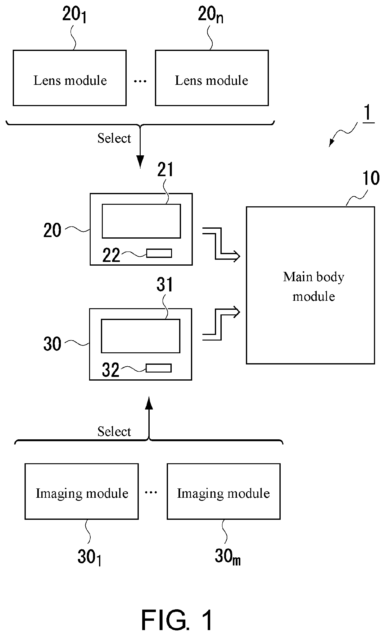
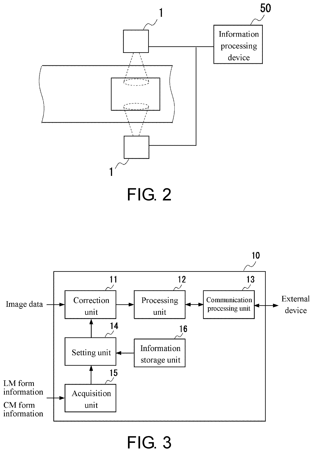
[0029]FIG. 1 illustrates a schematic configuration of an image sensor 1 according to the present embodiment, and FIG. 2 illustrates an example of the use of the image sensor 1.
[0030]As illustrated in FIG. 1, the image sensor 1 of the present embodiment is a device configured by mounting a lens module 20 and an imaging module 30 on a main body module 10. In addition, as illustrated in FIG. 2, the image sensor 1 is developed on the assumption that the image sensor is used by being provided at a plurality of locations of a production line or the like and processing results of the respective image sensors 1 are collected by one information processing device 50.
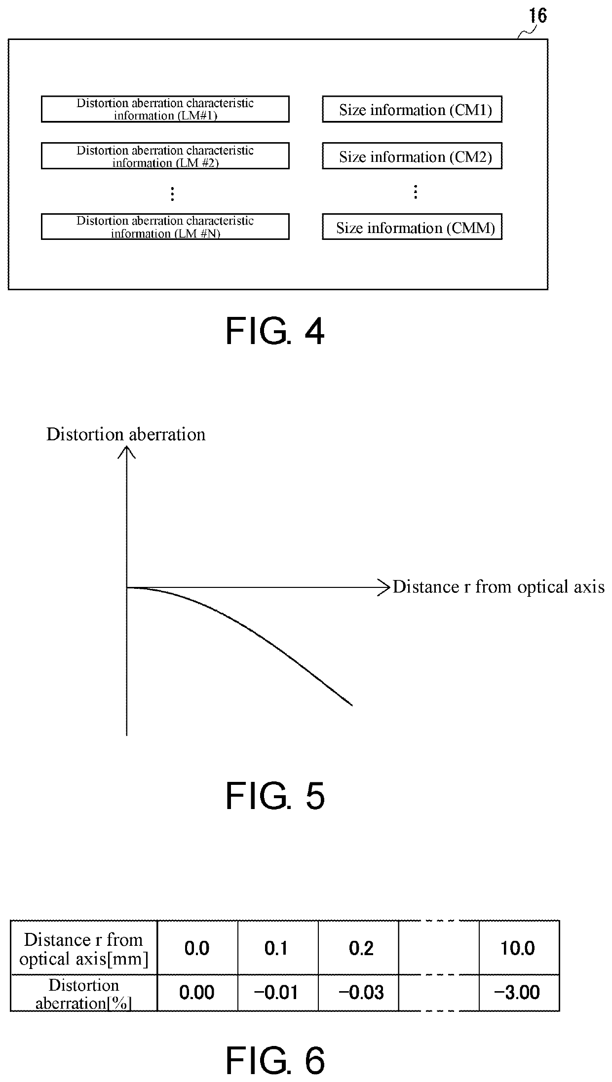
[0031]The imaging module 30 (FIG. 1) is a module including an imaging element 31 such as a CMOS image sensor or a CCD image sensor. As the imaging module 30 mountable on the main body module 10, imaging modules 301 to 30m of m types having different specifications of the imaging element 31 (a pixel size and the number of pixels (t...
second embodiment
[0054]Hereinafter, a configuration and operations of an image sensor 1 according to a second embodiment will be described focusing on portions different from those of the image sensor 1 according to the first embodiment by using the same reference numerals and signs as those used when the image sensor 1 according to the first embodiment is described. Meanwhile, for convenience of description, an image sensor 1 according to an L-th (L=1, 2) embodiment will also be hereinafter referred to as an L-th image sensor 1.
[0055]FIG. 9 illustrates a schematic configuration of a second image sensor 1 (the image sensor 1 according to the second embodiment).
[0056]The second image sensor 1 is a device which is configured by mounting a lens module 20 and an imaging module 30 on a main body module 10, similar to the first image sensor 1 (see FIG. 1). The imaging module 30 for the second image sensor 1 is the same as the imaging module 30 for the first image sensor 1. However, the lens module 20 for ...
modification example
[0064]Various modifications can be made to the image sensors 1 according to the above-described embodiments. For example, after an external device (the information processing device 50, other image sensors 1, a storage on the Internet, or the like) storing the distortion aberration characteristic correction information and the size information for each module is prepared, the main body module 10 of the image sensor 1 according to each of the embodiments may be modified to a module that acquires the information based on the lens module 20 and the imaging module 30 which are mounted thereon from the external device. Meanwhile, in a case where the main body module 10 of the image sensor 1 according to the first embodiment is modified to such a module, the information storage unit 16 is removed from the main body module 10, for example, as illustrated in FIG. 11, and the setting unit 14 may be modified to a unit that acquires the distortion aberration correction information and the size...
PUM
 Abstract
Description
Claims
Application Information
 - R&D
- Intellectual Property
- Life Sciences
- Materials
- Tech Scout
- Unparalleled Data Quality
- Higher Quality Content
- 60% Fewer Hallucinations
Browse by: Latest US Patents, China's latest patents, Technical Efficacy Thesaurus, Application Domain, Technology Topic, Popular Technical Reports.
© 2025 PatSnap. All rights reserved.Legal|Privacy policy|Modern Slavery Act Transparency Statement|Sitemap|About US| Contact US: help@patsnap.com