
Safety anchor and roof vent

a safety anchor and roof vent technology, applied in the direction of snow traps, lighting and heating apparatus, heating types, etc., can solve the problems of unsafe setting up, inability to support the requisite force applied by workers, and the safety line may become frayed and brittle, etc., to achieve the effect of safe completion

Active Publication Date: 2021-01-26
GIROUX MICHAEL
View PDF27 Cites 6 Cited by
  • Summary
  • Abstract
  • Description
  • Claims
  • Application Information

AI Technical Summary

Problems solved by technology

This set up is dangerous since the safety lines can rub across the ridge of the roof, which is usually shingled, and the safety line can become frayed and brittle.
Further, the object which the safety line is attached to may not be able to support the requisite force applied if a worker falls.
This presents an obvious safety hazard since the safety line may break and the worker will fall and become injured.

Method used


Image

  • Safety anchor and roof vent
  • Safety anchor and roof vent
  • Safety anchor and roof vent

Examples


Embodiment Construction

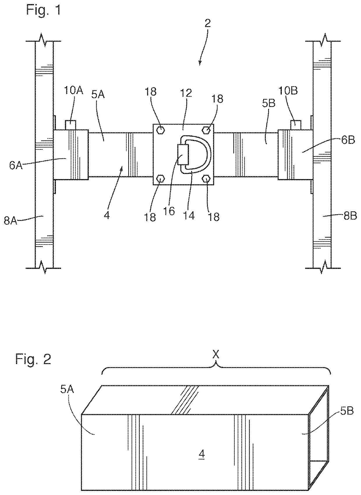
[0033]FIG. 1 shows a safety anchor apparatus 2 in accordance with one embodiment of the present invention. The safety anchor apparatus 2 is shown in top view. The safety anchor apparatus 2 has a support member 4 which has a first end 5A and a second end 5B. The first end 5A is supported by a first bracket 6A, and the second end 5B is supported by a second bracket 6B.

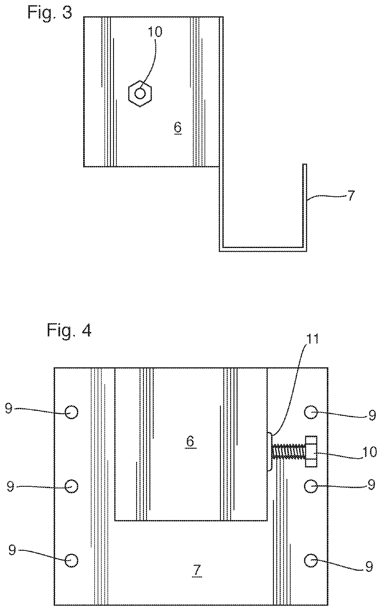
[0034]In one preferred embodiment, the support member 4 is a 2 inch by 2 inch square tube made of steel that is 3 / 16 inches thick. It is to be appreciated that the support member 4 could be sized and formed of appropriate material to provide enough rigidity and strength to withstand forces that would be applied if a worker slipped or fell and a force was exerted on the support member, plus a factor of safety. As shown, the first bracket 6A and second bracket 6B are square tubes sized to accept the respective first end 5A and second end 5B.

[0035]As shown in FIG. 2, the support member 4 is a square steel beam that can be s...


PUM


Abstract

An anchor support and roof vent for a pitched roof, comprising a support member having a first end and a second end, the support member being sized so that the first end is fixable to a first roof truss and the second end is fixable to a second roof truss, an anchor line attachment fixable to the support member, and a roof vent cover attachable over the anchor support member.

Description

FIELD OF THE INVENTION[0001]This invention relates to a safety anchor and roof vent. More particularly, this invention relates to a safety anchor device that enables a worker to attach a safety anchor line to the device, for example when working on the roof, and selectively acts as a roof vent that enables the venting of air from an attic space of a building.BACKGROUND OF THE INVENTION[0002]When workers are working on the roofs of buildings and in particular, residential and commercial buildings which have pitched roofs, they typically use an anchor line and harness system for safety in the event of a slip or fall. These anchor lines must be secured at an end opposite the worker such that the line will withstand the forces which may be applied to them should they be required to suddenly support the worker if he or she slips and / or falls.[0003]In the past, workers such as roofers have tied safety lines to objects such as trees or cars on an opposite side of a building on which they a...

Claims


Application Information

Patent Timeline
Patent Type & Authority Patents(United States)
IPC IPC(8): A62B35/00F24F7/02E04D13/12E04G21/32
CPCA62B35/0068E04D13/12E04G21/3214F24F7/02
Inventor GIROUX, MICHAEL
Owner GIROUX MICHAEL
Learn More