Solar thermal collector and mounting frame

A technology for solar collectors and mounting brackets, which is applied to the safety of solar collectors, solar collectors, fixed bases/supports of solar collectors, etc., and can solve problems such as displacement of heat-absorbing plates and inability to completely eliminate them

Inactive Publication Date: 2008-06-11
VKR HLDG AS
View PDF2 Cites 2 Cited by
  • Summary
  • Abstract
  • Description
  • Claims
  • Application Information

AI Technical Summary

Problems solved by technology

[0004] Known heat sinks that are simply placed on an insulation layer such as rock wool and have a flexible connection between Heat absorbing panels shift during process on roof etc.
Elastic fasteners reduce the risk of the sink shifting during transport or installation, but cannot completely eliminate the problem

Method used


Image

  • Solar thermal collector and mounting frame
  • Solar thermal collector and mounting frame
  • Solar thermal collector and mounting frame

Examples


Embodiment Construction

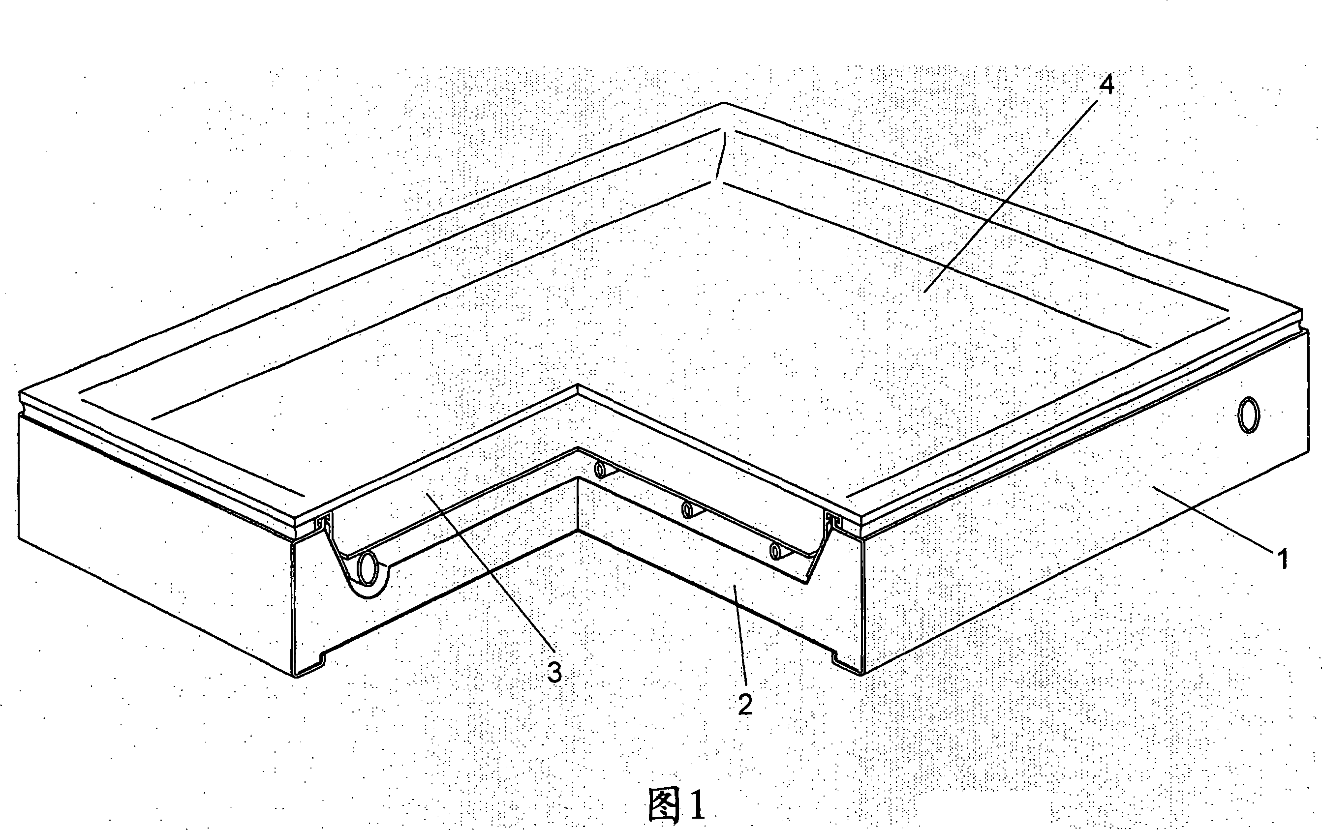
[0030] Preferred embodiments of the invention are described below with specific reference to flat plate collector assemblies, however it should be understood that other types of heat sinks may be employed with minimal changes in construction.

[0031] Figure 1 shows a flat panel solar collector by way of illustrative example. As shown in the sectional perspective view in FIG. 1 , the solar heat collector has: a frame 1 , a heat insulating layer 2 , a heat absorbing plate 3 and a cover plate 4 . The frame, insulation and cover form a housing with enclosures. The fence is used to provide support for the heat sink and protect the heat collector from heat loss due to wind, and also has an important role in keeping the moisture generated by rain, snow, and dew out of the heat collector .

[0032] The thermal insulation layer 2 consists of rigid polyurethane foam (PUR) or polyisocyanurate foam (PIR). These materials have excellent insulation value per unit thickness and are easy ...


PUM


Abstract

A solar collector with a rectangular frame (1), preferably made of extruded or rollformed metal, containing an absorber plate (3), an insulating layer (2) beneath the absorber plate (3), and a cover pane (4) spaced above the absorber (3). Absorber tubing (3b.3c) is attached to the rear side of the absorber plate. The absorber (3) is secured to the frame (1) by mounting brackets (11a,11b) that engage the absorber tubing (3b,3c) and allow for substantially unhindered thermal expansion and contraction of the absorber. The collector can be integrated or roof mounted on a pitched roof, or may be installed on a flat roof by means of a mounting frame.

Description

technical field [0001] The present invention relates to solar thermal collectors and mounting brackets, and in particular to a solar thermal collector comprising a rectangular frame, preferably of extruded or roll-formed metal, comprising: Insulation below the heat plate and a cover plate spaced from and above the heat sink. A heat sink pipe is attached to the rear side of the heat sink plate. The collector can be integrally formed with or mounted on a pitched roof, or mounted on a flat roof with mounting brackets. Background technique [0002] WO 2004 / 111550 discloses such a type of solar collector. The heat sink is simply plugged into the frame or into another housing. The heat sink is held in place by connecting the heat sink tubes to the frame, but it is also known to hold the heat sink in place by embedding it in insulating material. [0003] Neither of the above methods for securing the heat sink is ideal. A rigid connection between the heat sink tubes and the fra...

Claims


Application Information

Patent Timeline
Patent Type & Authority Applications(China)
IPC IPC(8): F24J2/26F24J2/46F16L3/18F16L3/20F24S10/75
CPCY02B10/20F16L3/20F24J2/26F16L3/18Y02E10/44F24J2002/5275F24J2/464F24J2/52F24J2/4647Y02E10/47F24J2/4636F16L3/1041F24S40/80F24S25/00F24S80/30F24S80/40F24S10/75F24S2025/011
Inventor 布伦特·默勒佩尔·雅各布森约翰尼·尼高
Owner VKR HLDG AS
Why Eureka
Try Eureka